MicoAir H743 AIO — User Manual
An AIO puts the flight controller and the 4-in-1 ESC on a single board. One board instead of a stack, one battery connection, no ribbon cable between the two halves, and a 25.5 × 25.5 mm mounting pattern that fits frames a 30.5 × 30.5 stack will not.
Both boards pair an STM32H743 flight controller with dual BMI088 + BMI270 IMUs and a 32-bit AM32 4-in-1 ESC.
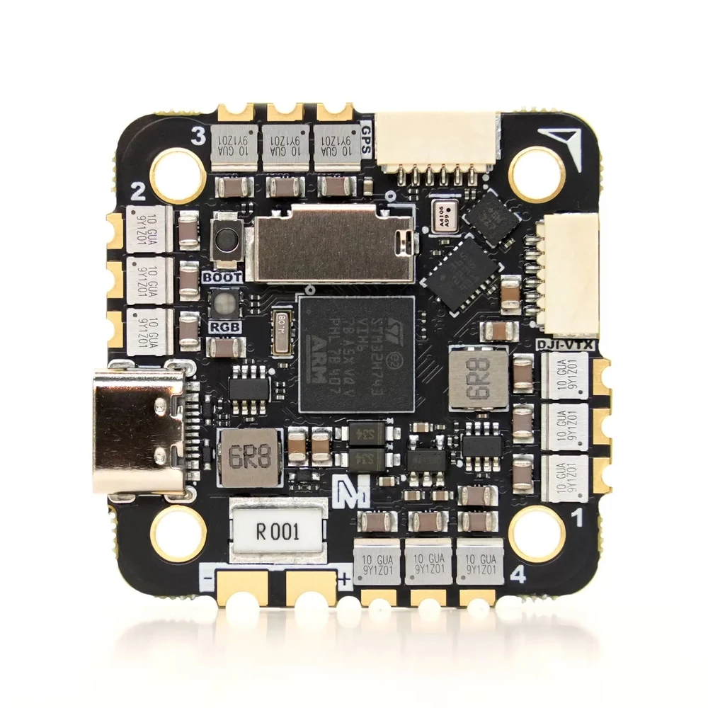
The two boards
| MicoAir743-AIO-35A | MicoAir743v2-AIO-45A | |
|---|---|---|
| ESC current | 35 A × 4 | 45 A × 4 |
| Barometer | DPS310 | SPL06 |
| ArduPilot target | MicoAir743-AIO | MicoAir743v2 |
| UARTs | 1, 2, 3, 4, 6, 7, 8 (UART7 = ESC telemetry, internal) | 1, 2, 3, 4, 5, 6, 8 |
| ESC firmware | AM32_MICOAIR_743_AIO_F421_2.17 | AM32_F4A_4IN1_F421_2.19 |
| ESC MCU | AT32F421 | — |
Everything else is shared:
| Item | Specification |
|---|---|
| MCU | STM32H743VIH6, 480 MHz, 2 MB flash |
| IMU | BMI088 + BMI270 (dual) |
| Compass | None on board — external via I2C |
| Analog OSD | None — HD only, over MSP DisplayPort |
| Logging | microSD card slot |
| Outputs | M1–M8, DShot and bi-directional DShot in hardware |
| Other | 1× I2C, 1× SWD, 2× ADC, LED strip pad, buzzer, BOOT button |
| USB | Type-C |
| ESC | 48 kHz PWM; PWM / DShot300 / DShot600 / bi-directional DShot |
| Battery input | 3–6S (≈ 10–27 V) |
| BEC | 5 V 2 A + 12 V 2 A |
| HD VTX | SH1.0-6P, MSP DisplayPort on UART2, 12 V on pin 1 |
| Mounting | 25.5 × 25.5 mm, Φ3 mm |
| Dimensions / weight | 36 × 36 × 8 mm / 10 g |
| Firmware | ArduPilot, PX4, INAV, Betaflight, Skybrush |
The 743-AIO-35A has its own ArduPilot target, MicoAir743-AIO. The 743v2-AIO-45A does not — it shares MicoAir743v2 with the standalone flight controller, so there is no AIO-named target to pick for it.
That means the obvious instinct is wrong in both directions: on one board you must use the AIO target, and on the other there is no AIO target and choosing something AIO-shaped would be a mistake. Read the target name character by character. See the Firmware Flashing Guide.
Where to buy
Ships from Canada with free Canada-wide shipping:
- MicoAir H743 V2 AIO with 45A AM32 ESC — ArduPilot pre-installed
- MicoAir H743 AIO 35A AM32
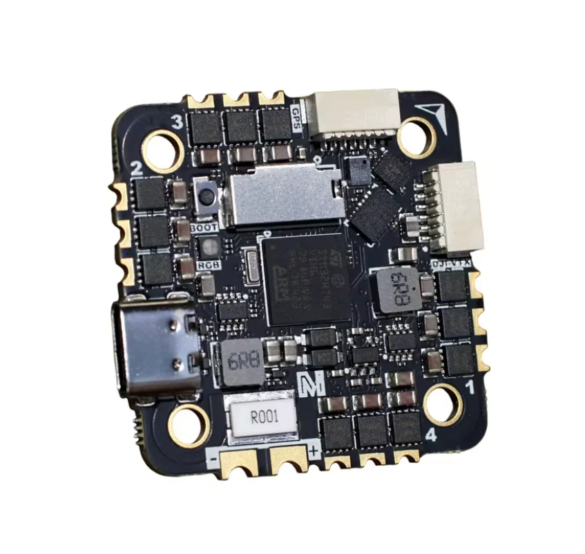
What an AIO trades away
Worth knowing before you choose one over a stack.
No compass. The standalone H743 V2 has a QMC5883L on board; these do not. For GPS flight you need an external compass on the I2C pads — which is what most serious builds use anyway, since a compass next to power wiring is a compromised compass.
This has a second consequence that catches people: ArduPilot's automatic compass orientation detection cannot work, because it deduces the external compass's rotation by comparing it against a working internal compass. With no internal compass there is nothing to compare against. Set COMPASS_ORIENT by hand — see External Compass Orientation, which covers the AIO case specifically.
No analog OSD. There is no AT7456E, so an analog video feed gets no overlay. These boards are built for HD: MSP DisplayPort on UART2 to a DJI O3/O4 or similar. ArduPilot's default OSD type on these boards is already MSP DisplayPort (OSD_TYPE = 5).
Less BEC current. 5 V at 2 A, against 3 A on the standalone H743 V2. Enough for a receiver, GPS and a sensor or two; worth checking if you plan to hang much off the 5 V rail.
Repairs are all-or-nothing. A damaged ESC channel on a stack means replacing the ESC. On an AIO it means replacing everything.
In exchange you get a smaller, lighter, simpler build with one less connector to come loose.
Mounting
- 25.5 × 25.5 mm, Φ3 mm holes, on insulated soft standoffs. Do not let a screw or a carbon plate touch pads or components.
- Board arrow toward the nose, component-marked side up. Mounted any other way, set the board orientation — see Flight Controller Board Orientation.
- Keep the ESC MOSFET area ventilated. Do not cover it with foam, double-sided tape or a wiring loom. The continuous current rating assumes the board can shed heat, and on an AIO the ESC is sitting directly under your flight controller.
Power
| Pad | Voltage | For | Watch out |
|---|---|---|---|
| VBAT | 3–6S (≈10–27 V) | main power for board and ESC | Never reverse polarity — check before the first connection |
| 5V | 5 V | receiver, GPS, optical flow, rangefinder | total load ≤ 2 A |
| 12V | 12 V | DJI O3 / O4 / O4 Pro, cameras | never to a 5 V-only device |
| GND | 0 V | power and signal ground |
Check the plug direction and pin order against the interface diagram before connecting a video transmitter. Getting it wrong can destroy the video transmitter and the board together.
UART mapping (ArduPilot)
MicoAir743v2-AIO-45A:
| ArduPilot | Physical | Default use |
|---|---|---|
| SERIAL0 | USB | ground station |
| SERIAL1 | UART1 | MAVLink2 |
| SERIAL2 | UART2 | DisplayPort (HD VTX) |
| SERIAL3 | UART3 | GPS |
| SERIAL4 | UART4 | MAVLink2 |
| SERIAL5 | UART5 | general purpose |
| SERIAL6 | UART6 | RC input |
| SERIAL8 | UART8 | general purpose |
MicoAir743-AIO-35A:
| ArduPilot | Physical | Default use |
|---|---|---|
| SERIAL0 | USB | ground station |
| SERIAL1 | UART1 | MAVLink2 |
| SERIAL2 | UART2 | VTX-HD / DisplayPort |
| SERIAL3 | UART3 | GPS |
| SERIAL4 | UART4 | MAVLink2 |
| SERIAL5 | UART6 | RC input |
| SERIAL6 | UART7 | ESC telemetry — internal, already wired |
| SERIAL7 | UART8 | general purpose |
Note the 35A board wires ESC telemetry internally on UART7. That is a genuine AIO advantage: on a stack it is a wire you have to remember.
Outputs
M1–M8, all supporting DShot and bi-directional DShot in hardware — whether you can use bi-directional DShot depends on the flight controller firmware (ArduPilot and Betaflight yes; PX4 and INAV not currently).
Timer groups, which must share a compatible protocol and frequency:
| Group | Outputs |
|---|---|
| 1 | 1, 2, 3, 4 |
| 2 | 5, 6 |
| 3 | 7, 8 (plus the LED pad, PWM11, on the 45A board) |
On the 45A board, configuring the LED pad for serial LEDs constrains outputs 7 and 8 to compatible settings.
ESC protocol
Start with DShot300. The integrated AM32 ESC does not accept the flight controller's default PWM output — set the protocol before you wonder why nothing spins.
ArduPilot's hardware definition for the MicoAir743-AIO target sets the default frame type to BetaFlightX, not standard X. The two put every output on a different corner:
| Output | Standard X | BetaFlightX |
|---|---|---|
| M1 | front right, CCW | rear right, CW |
| M2 | rear left, CCW | front right, CCW |
| M3 | front left, CW | rear left, CCW |
| M4 | rear right, CW | front left, CW |
Choose whichever matches how you actually wired the motors, then confirm it with the motor test before fitting propellers.
Receiver
UART6 is the default RC input.
| Protocol | Wiring | Notes |
|---|---|---|
| SBUS | signal → RX6 | one-way signal, plus power and GND |
| CRSF / ELRS | receiver TX → RX6, receiver RX → TX6 | telemetry supported |
| FPort | signal → TX6 | single-wire bidirectional |
| DSM / SRXL | signal → RX6 | check the receiver's supply voltage |
| SRXL2 | signal → TX6 | set the serial options ArduPilot requires |
| PPM | not supported | use a serial receiver protocol |
To move RC to another UART on ArduPilot, set that port's SERIALn_PROTOCOL = 23 and change the original RC port's protocol to something else — then re-check failsafe behaviour before flying.
Battery monitoring
Both boards ship with the same scaling:
| Parameter | ArduPilot / PX4 | Betaflight / INAV |
|---|---|---|
| Voltage factor | 21.12 | 211 |
| Current factor | 14.14 | 707 |
On a stack, the flight controller's default current scaling is a guess about an ESC it has never met, and is usually wrong. Here the ESC is part of the board, so the default describes the sensor that is genuinely fitted. Still verify it: compare the mAh the flight controller reports with what your charger puts back in, and scale the current factor by the ratio.
Firmware
| Firmware | Target |
|---|---|
| ArduPilot | MicoAir743-AIO (35A) · MicoAir743v2 (45A) — official from 4.6.0 |
| PX4 | micoair_h743-v2 — official from 1.16.0 |
| INAV | MICOAIR743V2_EXTMAG — from 8.0.1 RC1 |
| Betaflight | MicoAir743v2 builds |
| Skybrush | ArduPilot-derived, for drone light shows |
Note the INAV target ends in _EXTMAG — the external-magnetometer build, which is the correct choice here precisely because these boards have no internal compass. An intmag build would never see your GPS module's compass.
Flashing procedure, DFU mode and file formats: Firmware Flashing Guide.
Easily confused points
The two AIOs use different ArduPilot targets. MicoAir743-AIO for the 35A; MicoAir743v2 for the 45A. There is no MicoAir743v2-AIO target.
No compass means no compass auto-detection. Set COMPASS_ORIENT manually.
INAV needs the _EXTMAG build, for the same reason.
No analog OSD. HD DisplayPort or no overlay.
5 V is 2 A here, not 3 A. Less headroom than the standalone board.
"X" and "BetaFlightX" are different frame types and this board defaults to the second.
The ESC is under the flight controller. Its heat has nowhere else to go — leave the MOSFET area uncovered.
Troubleshooting
| Symptom | Where to look |
|---|---|
| Motors do nothing | ESC protocol not DShot300; flight battery not connected (USB does not power the ESC). |
| Motors on the wrong corners | Frame type — standard X vs BetaFlightX. Confirm with the motor test. |
| Compass not detected | External compass wiring on I2C; on INAV/Betaflight, the wrong build (intmag instead of extmag). |
| Heading wrong by a constant angle | COMPASS_ORIENT — auto-detection cannot work on this board. |
| No OSD on an analog feed | There is no analog OSD chip. HD only. |
| USB not recognised | Charge-only cable, or an under-powered hub. Try a data cable in a direct port. |
| Board runs hot under load | ESC ventilation — check nothing covers the MOSFET area. |
Related guides
- MicoAir H743 V2 Flight Controller — User Manual — the standalone board
- MicoAir 4-in-1 AM32 ESC — User Manual — the separate 55A and 70A boards
- Configuring ESC Parameters
- Firmware Flashing Guide
- External Compass Orientation
- F405 V2 — Beginner ArduPilot Setup Guide — the setup order applies here too
Written and maintained by the Robofusion engineering team.