NxtPX4 V2 Mini Flight Controller — User Manual
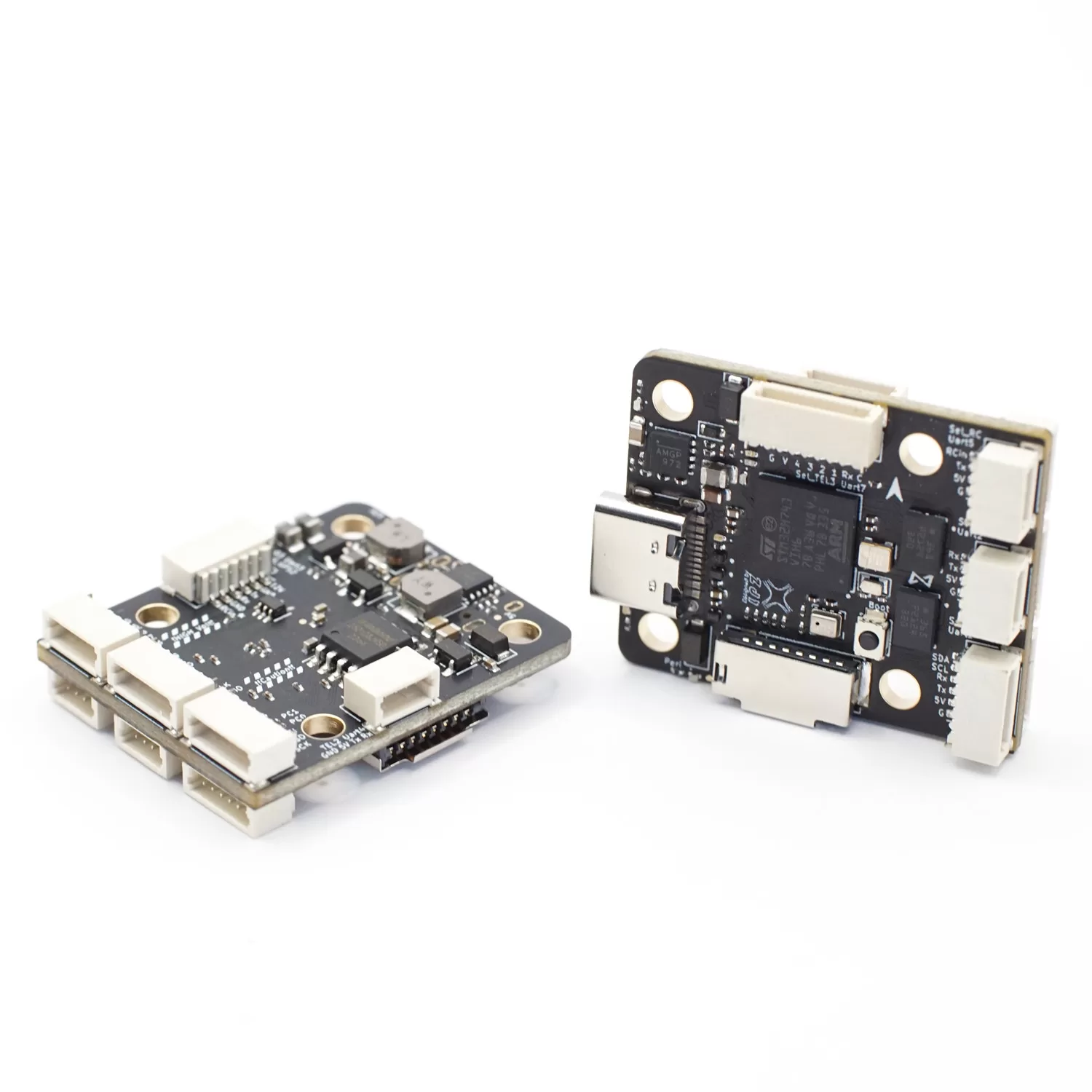
The NxtPX4 V2 (board name: NxtPX4v2) is a 20×20 mm mini flight controller with full-size H7 performance, designed as open-source hardware by the HKUST UAV Group and manufactured by MicoAir. It was created for a specific audience: researchers and developers building small PX4 drones — VIO (visual-inertial odometry), swarm, and autonomy work — who need clean dual-IMU data, a hardware design they can inspect and modify, and a board that fits airframes where a 30.5×30.5 stack won't. It runs PX4 natively (hardware follows the PX4-V6 standard) and is also officially supported by ArduPilot.
Where to buy
- Robofusion store (ships from Canada — free Canada-wide shipping): NxtPX4 V2 Mini Flight Controller
Most FPV flight controllers are closed designs: you get the board, not the schematic. The NxtPX4 V2's full hardware design is public, which means a lab can verify signal paths, add custom sensors, or respin the board for a project — no reverse-engineering. Following the PX4-V6 hardware standard means mainline PX4 firmware runs without vendor patches, and future PX4 releases keep working. HKUST also maintains a modified branch that publishes IMU data to ROS at 500 Hz — exactly what VIO pipelines want.
NxtPX4 V2, H743 V2, or F405 V2 — which one?
| NxtPX4 V2 | H743 V2 | F405 V2 | |
|---|---|---|---|
| Processor | STM32H743, 480 MHz | STM32H743, 480 MHz | STM32F405, 168 MHz |
| IMU | BMI088 × 2 (dual) | BMI088 + BMI270 (dual) | BMI088 |
| Firmware | PX4 (native) / ArduPilot | ArduPilot / PX4 / INAV / Betaflight | ArduPilot / INAV |
| Mounting | 20 × 20 mm, Φ3 | 30.5 × 30.5 mm | 30.5 × 30.5 mm |
| Weight | 6.5 g | 10 g | 9 g |
| OSD chip | None (HD DisplayPort only) | AT7456E + DisplayPort | AT7456E + DisplayPort |
| Best for | Small PX4 research / VIO drones | Do-it-all flagship | Budget long-range |
Specifications
| Item | Specification |
|---|---|
| MCU | STM32H743VIH6, 480 MHz, 2 MB flash |
| IMU | 2× BMI088 (dual, independent) |
| Barometer | SPL06 |
| Logging | MicroSD card slot |
| Interfaces | 7× UART, 8× PWM, 1× I2C, 1× SPI, 1× SWD, 2× ADC |
| USB | Type-C |
| HD VTX connector | SH1.0-6P for DJI O3 Air Unit (DisplayPort) |
| BEC | 5 V 2.5 A (peripherals) + 12 V 2.5 A (VTX, camera) |
| Battery input | 3–6S LiPo, on-board voltage sensing |
| Compass | None built-in — connect external via I2C (SDA/SCL) |
| GPIOs | 3 on the AUX connector (ArduPilot pins 81/82/83) |
| Mounting | 20 × 20 mm, Φ3 mm holes |
| Dimensions / weight | 27 × 32 × 8 mm / 6.5 g |
| Hardware design | Open source (HKUST Nxt-FC), PX4-V6 standard |
The 5 V and 12 V BEC rails come up only when the main battery is connected. On USB alone the board itself runs and a ground station will connect happily — but the GPS, the external compass, the receiver and the video transmitter all stay dark.
This produces one of the most misleading symptoms in the whole build process: the flight controller is clearly working, yet the compass "isn't detected" and the GPS "is broken". Before you troubleshoot anything peripheral-shaped on this board, plug in the battery, then connect USB and look again.
Pinout
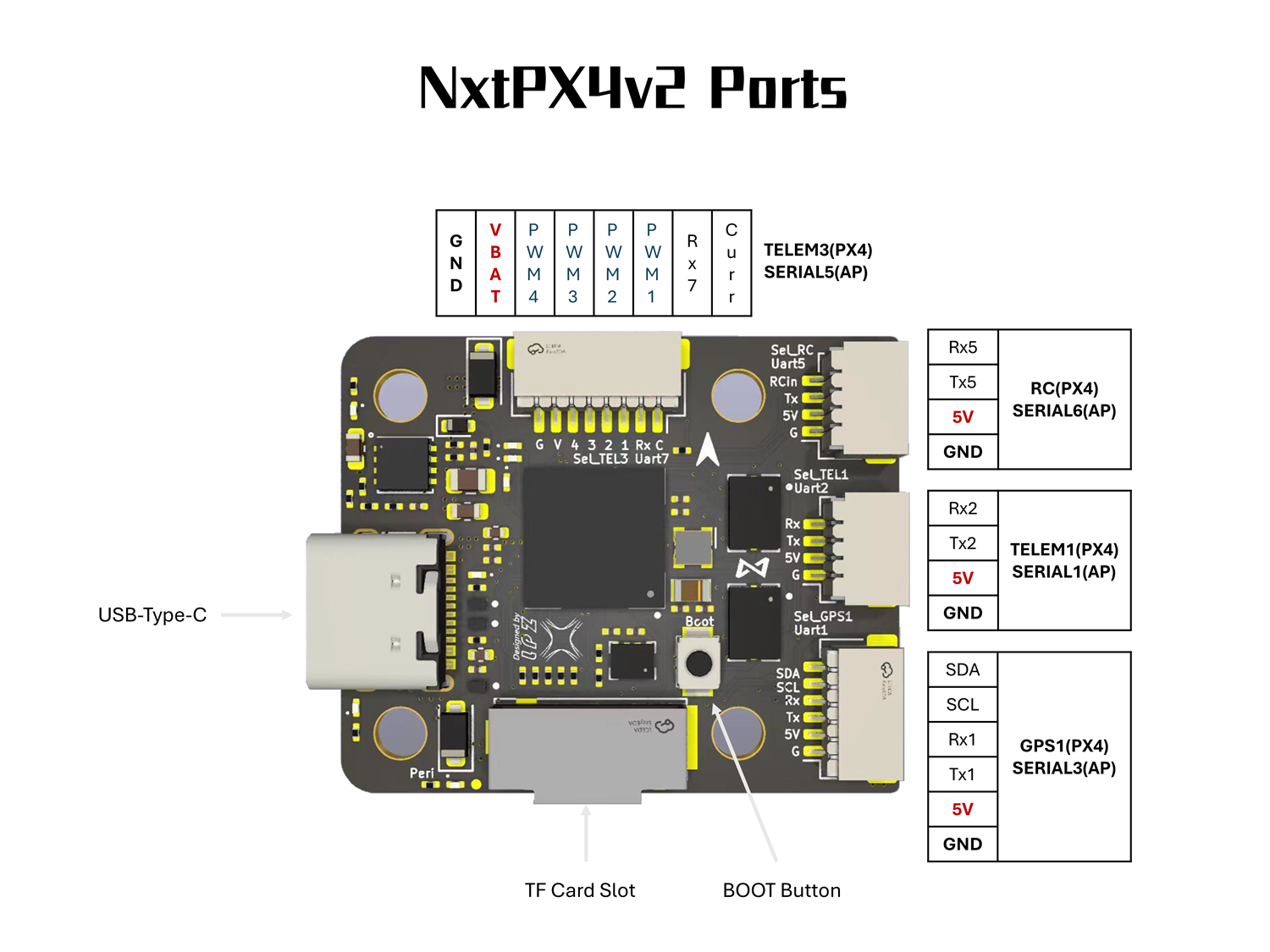
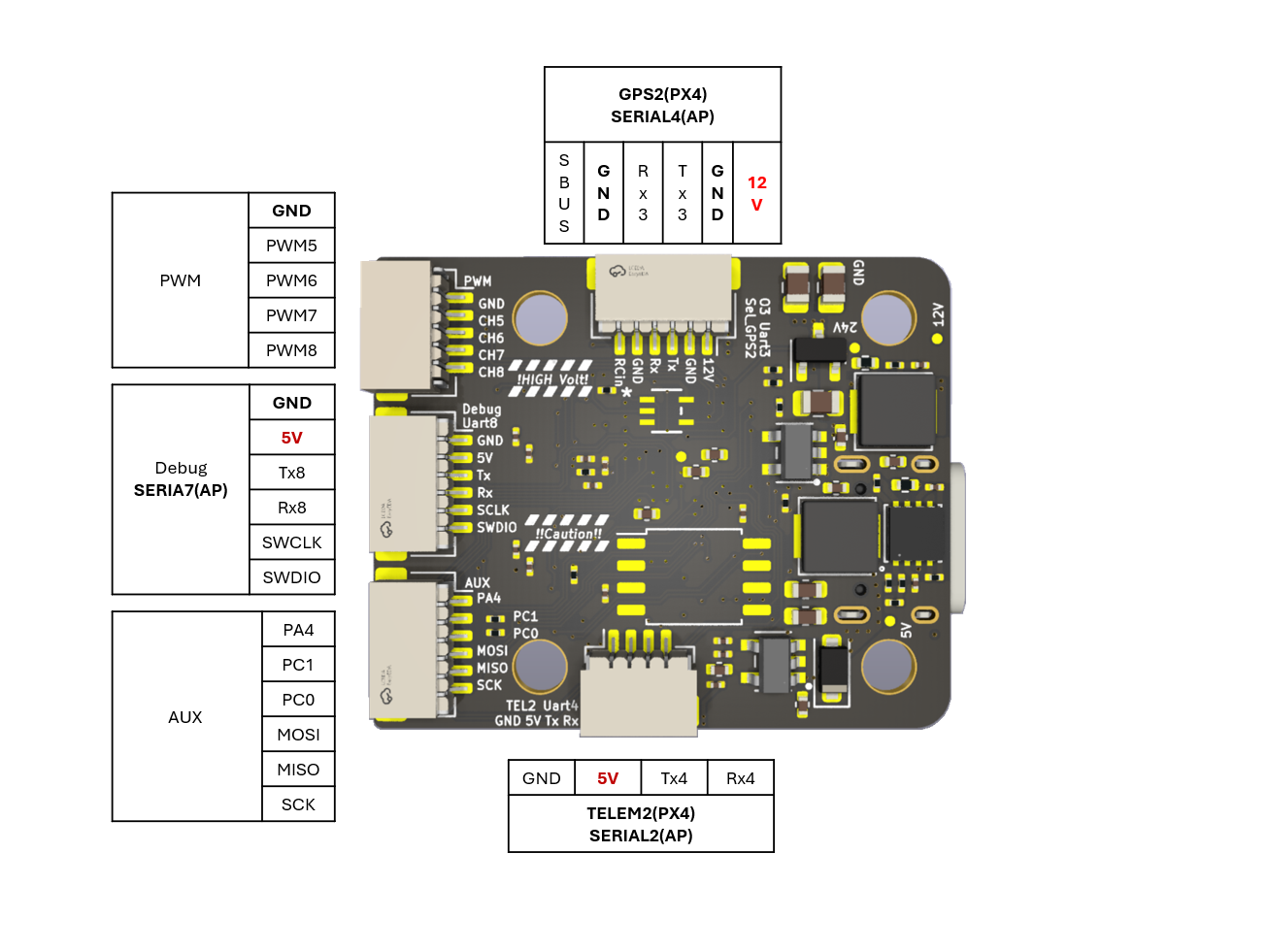
Front and back pad layout:
Connector pin list
Pins are listed in the order printed on MicoAir's port diagram. Before plugging anything in, match the first and last pin against the silkscreen next to the connector — the diagram shows which end is which, a text table cannot.
| Connector | Pins | Port (ArduPilot / PX4) | Notes |
|---|---|---|---|
| ESC (8-pin) | GND · VBAT · PWM4 · PWM3 · PWM2 · PWM1 · RX7 · Curr | RX7 = SERIAL5 / TELEM3 | ESC telemetry on RX7 |
| PWM 5–8 | GND · PWM5 · PWM6 · PWM7 · PWM8 | — | |
| RC (UART5) | RX5 · TX5 · 5V · GND | SERIAL6 / RC | receiver |
| TELEM1 (UART2) | RX2 · TX2 · 5V · GND | SERIAL1 / TELEM1 | telemetry radio |
| GPS1 (UART1 + I2C) | SDA · SCL · RX1 · TX1 · 5V · GND | SERIAL3 / GPS1 | GPS plus external compass |
| TELEM2 (UART4) | GND · 5V · TX4 · RX4 | SERIAL2 / TELEM2 | |
| O3 / GPS2 (UART3, 6-pin) | SBUS · GND · RX3 · TX3 · GND · 12V | SERIAL4 / GPS2 | 12 V on this connector — DJI O3 air unit; SBUS is the air unit's RC output |
| Debug (UART8 + SWD) | GND · 5V · TX8 · RX8 · SWCLK · SWDIO | SERIAL7 | serial console and SWD |
| AUX | PA4 · PC1 · PC0 · MOSI · MISO · SCK | — | spare GPIO and the external SPI bus |
Also on the board: USB-C, the BOOT button and a microSD slot.
UART mapping
| Port | ArduPilot | PX4 | Default function |
|---|---|---|---|
| USB | SERIAL0 | — | GCS connection |
| UART2 | SERIAL1 | TELEM1 | MAVLink2 telemetry |
| UART4 | SERIAL2 | TELEM2 | MAVLink2 (companion computer) |
| UART1 | SERIAL3 | GPS1 | GPS |
| UART3 | SERIAL4 | GPS2 | DJI O3 (DisplayPort) |
| UART7 | SERIAL5 | TELEM3 | ESC telemetry (RX only) |
| UART5 | SERIAL6 | RC | RC receiver input |
| UART8 | SERIAL7 | TELEM4 / SERIAL4 | Spare (user) |
All UARTs are DMA-enabled. Note the deliberate numbering: physical UART2/UART4 are the MAVLink telemetry ports — on a research drone, that's one for the radio and one for the onboard computer.
RC input
UART5 is the default RC port:
- SBUS — the SBUS pin (hardware-inverted into RX5) works out of the box; on PX4 set
RC_INPUT_PROTO = Auto - CRSF / ELRS — wire RX5 and TX5; on ArduPilot set
SERIAL6_OPTIONS = 0(telemetry comes back automatically) - FPort — TX5 with
SERIAL6_OPTIONS = 7; SRXL2 — TX5 withSERIAL6_OPTIONS = 4 - PPM is not supported
RC can also be moved to UART2, UART4 or UART8 (SERIALn_PROTOCOL = 23, and change SERIAL6_PROTOCOL away from 23).
HD VTX
The SH1.0-6P connector carries a DJI O3 Air Unit connection with DisplayPort OSD. There is no analog OSD chip on this board — it's designed for HD video or camera-less research airframes.
Pin 1 of the SH1.0-6P connector carries the 12 V BEC rail. Never wire a 5 V peripheral to it.
PWM outputs and DShot
8 PWM outputs, all supporting bi-directional DShot (ArduPilot). Outputs are grouped — same protocol within a group:
| Group | Outputs |
|---|---|
| 1 | 1, 2, 3, 4 |
| 2 | 5, 6 |
| 3 | 7, 8 |
Battery monitoring
Built-in voltage sensing; current sensing via an external sensor on the Curr pin (typically from a 4-in-1 ESC). Default ArduPilot parameters:
| Parameter | Value |
|---|---|
BATT_MONITOR | 4 |
BATT_VOLT_PIN | 4 |
BATT_CURR_PIN | 8 |
BATT_VOLT_MULT | 10.2 |
BATT_AMP_PERVLT | 20.4 |
Note the values differ from the 30.5-size boards — don't copy parameters across models. The current scale in particular depends on the power module or ESC you actually fit: calibrate it with a multimeter and a known load rather than copying a figure from another autopilot.
The 12 V BEC has to step down from the pack. A 2S pack sits between 6.0 V and 8.4 V, which leaves nothing for a 12 V rail to work with — which is why the board is rated from 3S even though the voltage sensing itself copes with a wider range.
Compass
No compass on board. For outdoor GPS flight, add a GPS+compass combo on the external I2C bus (I2C4 — SCL on PD12, SDA on PD13). Indoor VIO-only research builds typically fly without one.
If the compass is not detected, check that the main battery is connected before blaming the wiring — on USB alone the external I2C bus has no power.
Firmware
| Firmware | Support | Target / notes |
|---|---|---|
| PX4 | Native | Build targets hkust_nxt-dual (bootloader: hkust_nxt-dual_bootloader); 500 Hz IMU ROS branch from HKUST |
| ArduPilot | Official from 4.6.0 | Target NxtPX4v2 — builds on firmware.ardupilot.org |
First-time flashing (DFU)
- Disconnect USB and battery.
- Hold the BOOT button, keep holding it, and plug in USB-C.
- Release once the computer enumerates the DFU device.
- Flash the
*_with_bl.hexfirmware with your DFU tool, or over DFU in MicoConfigurator. - Afterwards, update with
.apjfiles (ArduPilot) or through QGroundControl (PX4) over plain USB.
A board in DFU mode appears as a DFU device rather than a COM port, and its LEDs stay dark. Both are normal.
Easily confused points
USB power and peripheral power are not the same thing. This is the one that costs people an evening: the board runs on USB, the BECs don't. No battery means no GPS, no compass, no receiver, no VTX.
BATT_VOLT_MULT is 10.2 here, not 21.2. The voltage divider on this board is different from the 30.5 × 30.5 boards. Copying a battery parameter set across MicoAir models gives readings that are wrong by roughly a factor of two — which looks like a flat pack on a full one.
ArduPilot SERIAL numbers do not follow the UART numbers. SERIAL1 is UART2, SERIAL3 is UART1, SERIAL4 is UART3. Read the mapping table rather than assuming.
There is no analog OSD chip. HD DisplayPort or nothing — an analog VTX will give you video with no overlay.
Pin 1 of the HD VTX connector is 12 V. Wiring a 5 V peripheral to it destroys the peripheral.
"PX4 native" doesn't mean ArduPilot is second-class. Both are officially supported; the PX4-V6 lineage just means mainline PX4 runs without vendor patches.
FAQ
Is this board only for researchers?
No — it's also a solid pick for any small ArduPilot/PX4 build where 20×20 mounting and 6.5 g matter. But its distinctive features (open hardware, PX4-V6 compliance, 500 Hz IMU ROS topic) are aimed at autonomy work; if you just want a general-purpose FC, the H743 V2 gives you more UARTs, analog OSD and Bluetooth for similar money.
How do I connect a companion computer (Jetson / Pi)?
Wire the companion's UART to UART4 (TELEM2 on PX4) and set it up as a MAVLink port — the standard PX4 offboard-control path. UART2 stays free for a telemetry radio like the LR900.
The ground station connects, but my external compass isn't detected
Connect the main battery. The 5 V and 12 V rails that feed the external I2C bus only come up with the battery present, so on USB alone the compass has no power to answer on. Plug in the battery first, then USB, then re-scan.
Can it fly FPV with analog video?
Not directly — there's no analog OSD chip. Pair it with an HD system (DJI O3) via the HD VTX connector, or add an external OSD. For analog-first builds, choose the F405 V2 or H743 V2.
Related guides
- H743 V2 Flight Controller — User Manual
- F405 V2 Flight Controller — User Manual
- PX4 — Telemetry Setup Guide
- ArduPilot — Telemetry Setup Guide
Written and maintained by the Robofusion engineering team.