VT5804 5.8 GHz 2.5W Video Transmitter — User Manual
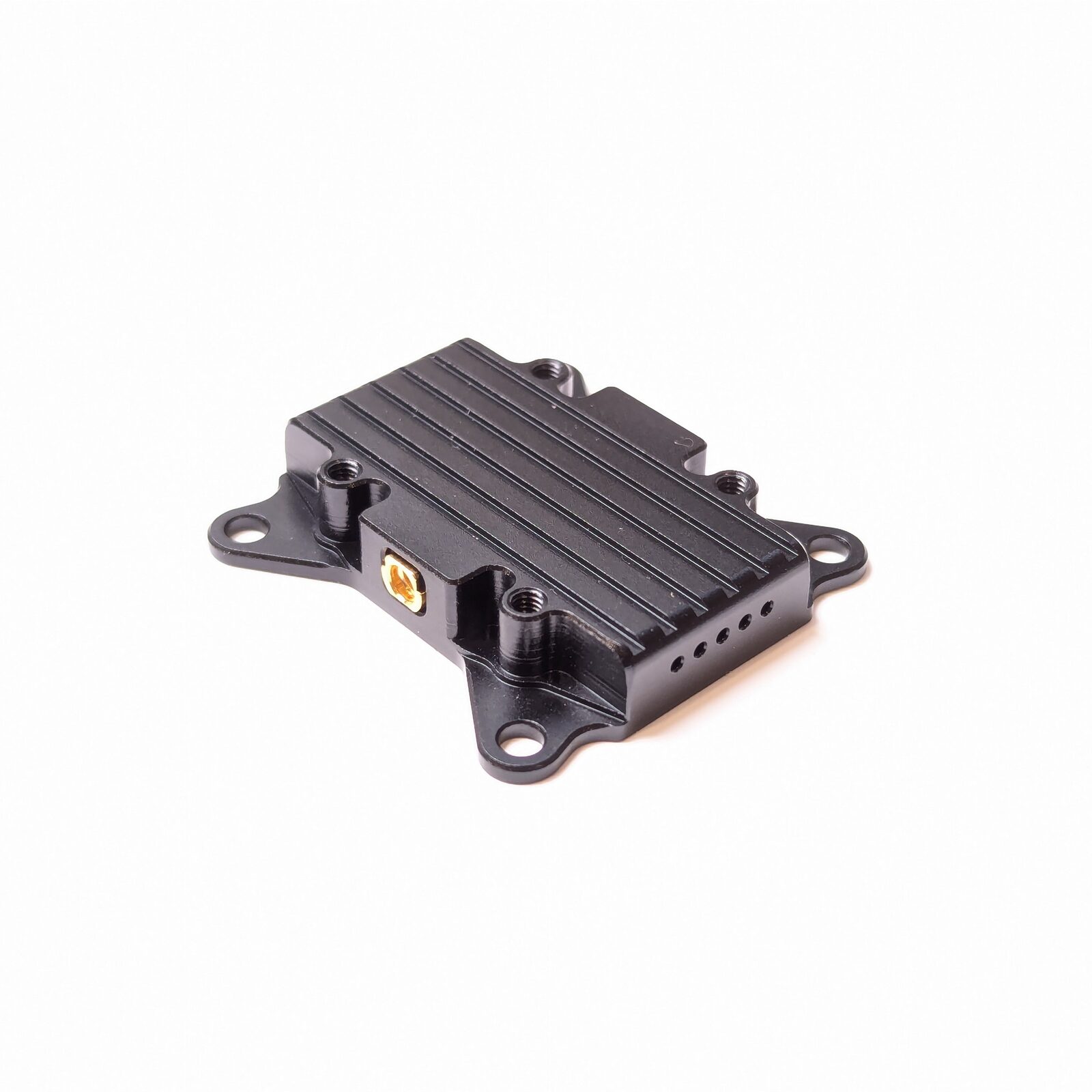
The VT5804 is a long-range 5.8 GHz analog video transmitter (VTX) module with selectable output power up to 2.5 W (2500 mW). It takes a standard CVBS analog video signal from an FPV camera, transmits it on any of 48 channels across 6 bands, and supports remote configuration through the TBS SmartAudio protocol. A wide 7–36 V input (2S–8S) and a regulated 5 V output for the camera make it a drop-in video link for fixed-wing aircraft, long-range quads, and industrial drones.
Where to buy
- Robofusion store (ships from Canada — free Canada-wide shipping): VT5804 2.5 W Video Transmitter Module — available as module only, or bundled with the A5800 antenna
An FPV (First-Person View) video link has three parts: a camera on the aircraft produces an analog video signal (CVBS — the same composite format old TVs used), a video transmitter (VTX) like the VT5804 broadcasts that signal over the air at 5.8 GHz, and a receiver in your goggles or ground monitor picks it up. Analog video adds almost no latency and degrades gracefully at the edge of range — which is why it remains popular for long-range and racing builds even in the digital era. Transmit power (mW) is the main lever for range: more power reaches farther but draws more current and makes more heat.
VT5804 or VT5805 — which one?
The VT5804 and VT5805 are the same platform at two power classes:
| VT5804 | VT5805 | |
|---|---|---|
| Max output power | 2.5 W (25/600/1200/2500 mW) | 4 W (25/1000/2000/4000 mW) |
| Cooling | Finned heatsink case | Heatsink case + built-in fan |
| Height / weight | 7.2 mm / 11 g | 13.5 mm / 16.9 g |
| Max current | 850 mA @ 12 V | 1100 mA @ 12 V |
| Best for | Weight-sensitive builds, medium-long range | Maximum range, larger airframes |
Everything else — bands, channels, wiring, SmartAudio, mounting pattern — is identical.
Specifications
| Item | Specification |
|---|---|
| Product name | VT5804 video transmitter module |
| Frequency band | 5.8 GHz (5362–5945 MHz, 48 channels / 6 bands) |
| Transmit power | 25 / 600 / 1200 / 2500 mW (4 levels) |
| Video format | CVBS (analog composite) input |
| Input voltage | 7–36 V (2S–8S) |
| Max current | 850 mA @ 12 V |
| Camera power output | 5 V regulated |
| Configuration protocol | TBS SmartAudio |
| Antenna connector | MMCX |
| Dimensions | 38 × 36.5 × 7.2 mm |
| Mounting hole pattern | 30.5 × 30.5 mm |
| Net weight | 11 g (excluding antenna) |
What's in the box
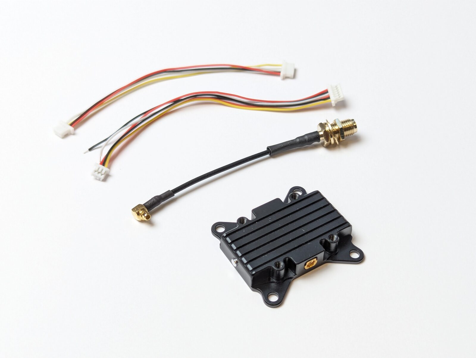
- 1 × VT5804 transmitter module
- 1 × 6-pin ribbon cable
- 1 × MMCX-to-RPSMA extension feeder cable
- 1 × product manual
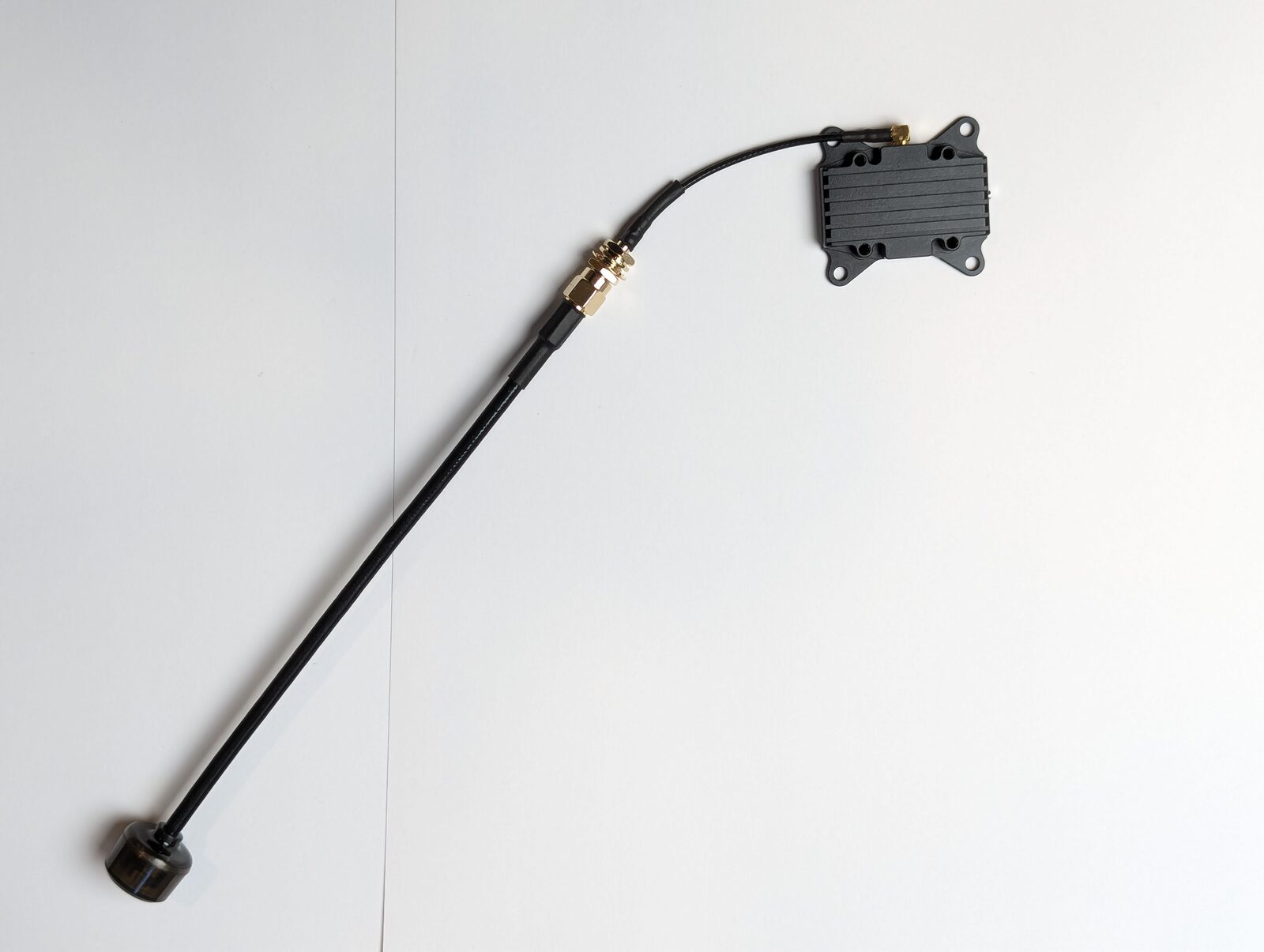
The VT5804 ships with an RPSMA extension feeder but no antenna. At 2.5 W, antenna quality directly affects range — pair it with a well-matched 5.8 GHz antenna rated for high power, such as the Robofusion A5800 omni dipole.
Wiring
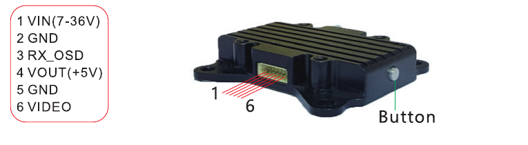
The VT5804 uses a single 6-pin connector. Pin 1 is marked on the case:
| Pin | Function |
|---|---|
| 1 | VIN — 7–36 V power input (DC IN) |
| 2 | GND — power input ground |
| 3 | RX_OSD — TBS SmartAudio (flight-controller configuration) |
| 4 | VOUT — 5 V power output (for the camera) |
| 5 | GND — power output ground |
| 6 | VIDEO — CVBS video signal input |
The pinout is also silk-screened on the underside of the case:
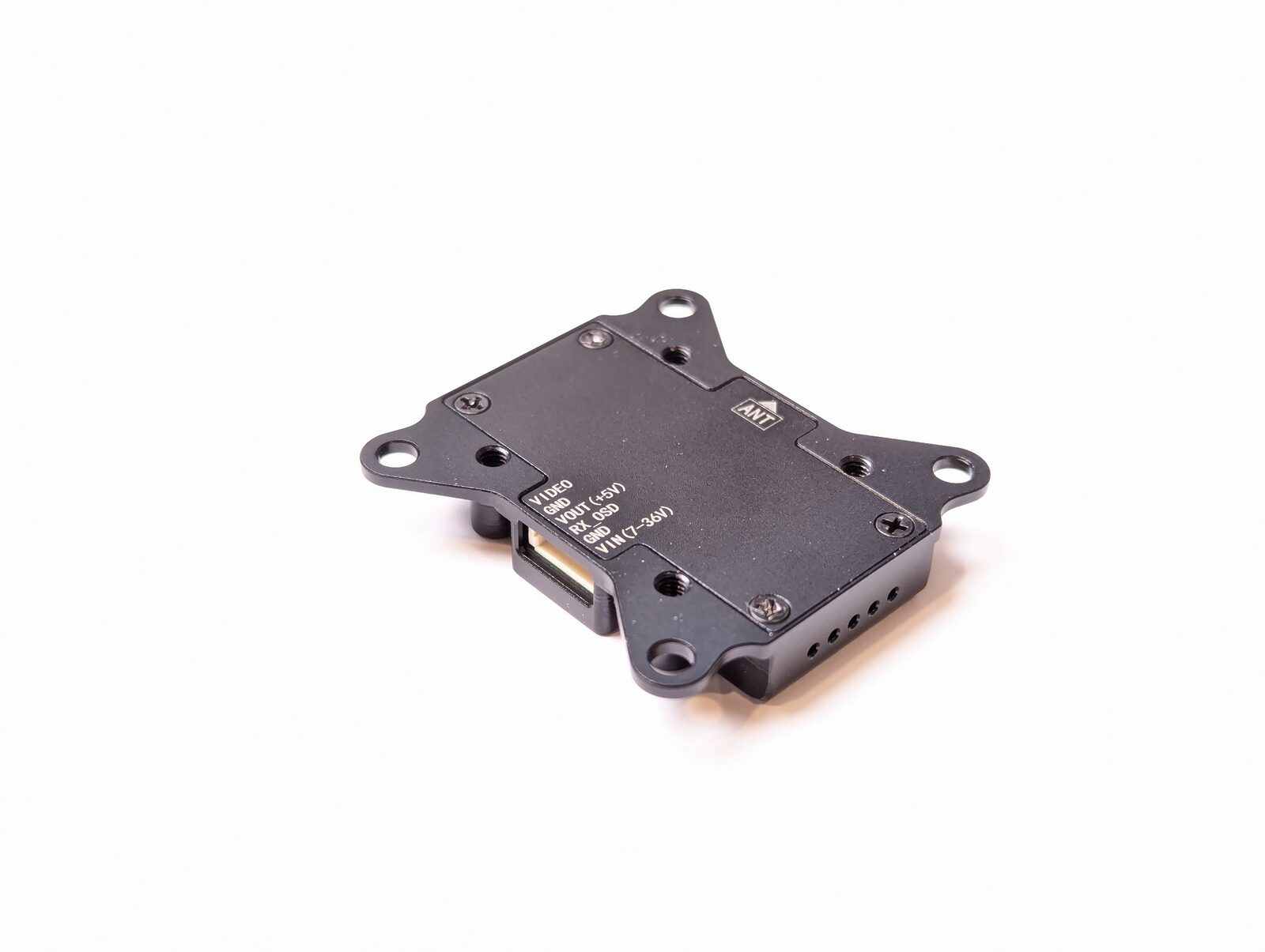
Typical hookup: battery (or PDB) → VIN/GND; camera video out → VIDEO; camera power → VOUT/GND (pin 4/5); flight-controller UART TX → RX_OSD if you want SmartAudio control.
Powering any VTX — especially a 2.5 W one — without an antenna attached reflects the RF energy back into the output stage and can permanently damage the module within seconds. Always attach the antenna (or the RPSMA extension with an antenna on it) before connecting power.
At 1200–2500 mW the heatsink gets hot by design. Mount the module where airflow can reach the fins, and avoid enclosing it in shrink-wrap or foam. On the bench, keep high-power test runs short — or test at 25 mW.
Bands, channels, and frequency table
The VT5804 covers 48 channels: 6 bands (groups) × 8 channels. Frequencies in MHz:
| Band | GR LED flashes | CH1 | CH2 | CH3 | CH4 | CH5 | CH6 | CH7 | CH8 |
|---|---|---|---|---|---|---|---|---|---|
| A | 1 | 5865 | 5845 | 5825 | 5805 | 5785 | 5765 | 5745 | 5725 |
| B | 2 | 5733 | 5752 | 5771 | 5790 | 5809 | 5828 | 5847 | 5866 |
| E | 3 | 5705 | 5685 | 5665 | 5645 | 5885 | 5905 | 5925 | 5945 |
| FS/IRC | 4 | 5740 | 5760 | 5780 | 5800 | 5820 | 5840 | 5860 | 5880 |
| RACE | 5 | 5658 | 5695 | 5732 | 5769 | 5806 | 5843 | 5880 | 5917 |
| LOW | 6 | 5621 | 5584 | 5547 | 5510 | 5473 | 5436 | 5399 | 5362 |
Every analog FPV receiver on the market uses this same standard grid, so any 5.8 GHz goggles can tune to the VT5804. Set the VTX and your receiver to the same band and channel and video appears. RACE (Raceband) spaces its channels 37 MHz apart, which minimizes cross-talk when several pilots fly at once. FS/IRC is the FatShark/ImmersionRC band. If you fly alone, almost any channel works — just avoid channels adjacent to other pilots nearby.
LED indicators
Five LEDs show the current configuration at a glance:
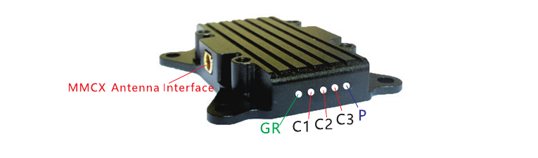
| LED | Meaning |
|---|---|
| P | RF power indicator |
| C3 / C2 / C1 | Channel indicators (binary combination) |
| GR | Group (band) indicator — number of blue flashes = band |
Channel readout — O = LED on, X = LED off (C3 C2 C1):
| Channel | 1 | 2 | 3 | 4 | 5 | 6 | 7 | 8 |
|---|---|---|---|---|---|---|---|---|
| C3 C2 C1 | X X X | X X O | X O X | X O O | O X X | O X O | O O X | O O O |
The blue GR LED's flash count indicates the band (1 flash = A … 6 flashes = LOW), and the green C1–C3 LEDs indicate the channel per the table above.
Button configuration
All settings can be changed with the single button on the side of the case:
| Action | What it does |
|---|---|
| Short press | Cycle through channels 1–8 |
| Hold 3 s (blue LED flashes, then release) | Enter band selection — short presses cycle A → LOW |
| Hold 6 s (blue LED turns off, red lights, then release) | Enter power selection — short presses cycle 25 / 600 / 1200 / 2500 mW; green flash count (1–4) shows the level |
| Hold 2 s (inside a selection mode) | Save and exit |
After changing band or power, always finish with the 2-second hold to save — otherwise the change is not stored.
SmartAudio — configure from your flight controller
Pin 3 (RX_OSD) speaks TBS SmartAudio, the de-facto standard for VTX remote control. Wire it to a spare UART TX pad on your flight controller and you can change band, channel, and power from your radio or OSD menu instead of the button:
- Betaflight / iNav: assign the UART to VTX (SmartAudio) in the Ports tab, then use the OSD or Vtx Tables.
- ArduPilot: set
VTX_ENABLE=1and the relevantSERIALn_PROTOCOL=37(SmartAudio), then control power/channel via parameters or the transmitter.
Changing channels via button presses on the flight line is slow and error-prone. With SmartAudio you can drop to 25 mW for bench work, then switch to full power on the arming switch — one less way to cook a module or stomp on another pilot's video.
Transmit power and the law
Higher power ≈ more range, but 5.8 GHz transmit-power limits vary by country. In the US, operation above 25 mW effectively requires an amateur (HAM) radio license; Canada and most of Europe have similar or stricter rules. Fly at 25 mW indoors, at races, and wherever other pilots share the air — save 1200/2500 mW for licensed long-range work in open areas. You are responsible for complying with local regulations.
FAQ
No video in my goggles — first checks?
Antenna attached, VTX and receiver on the same band and channel, camera powered (VOUT pin 4), and video signal wire on pin 6 (not swapped with a GND). If the OSD shows but no camera image, the problem is camera-side.
Can I power it straight from a 6S battery?
Yes — the 7–36 V input covers 2S–8S directly. The camera should be powered from the module's regulated 5 V output (pin 4), not from the battery.
Do I need the RPSMA extension cable?
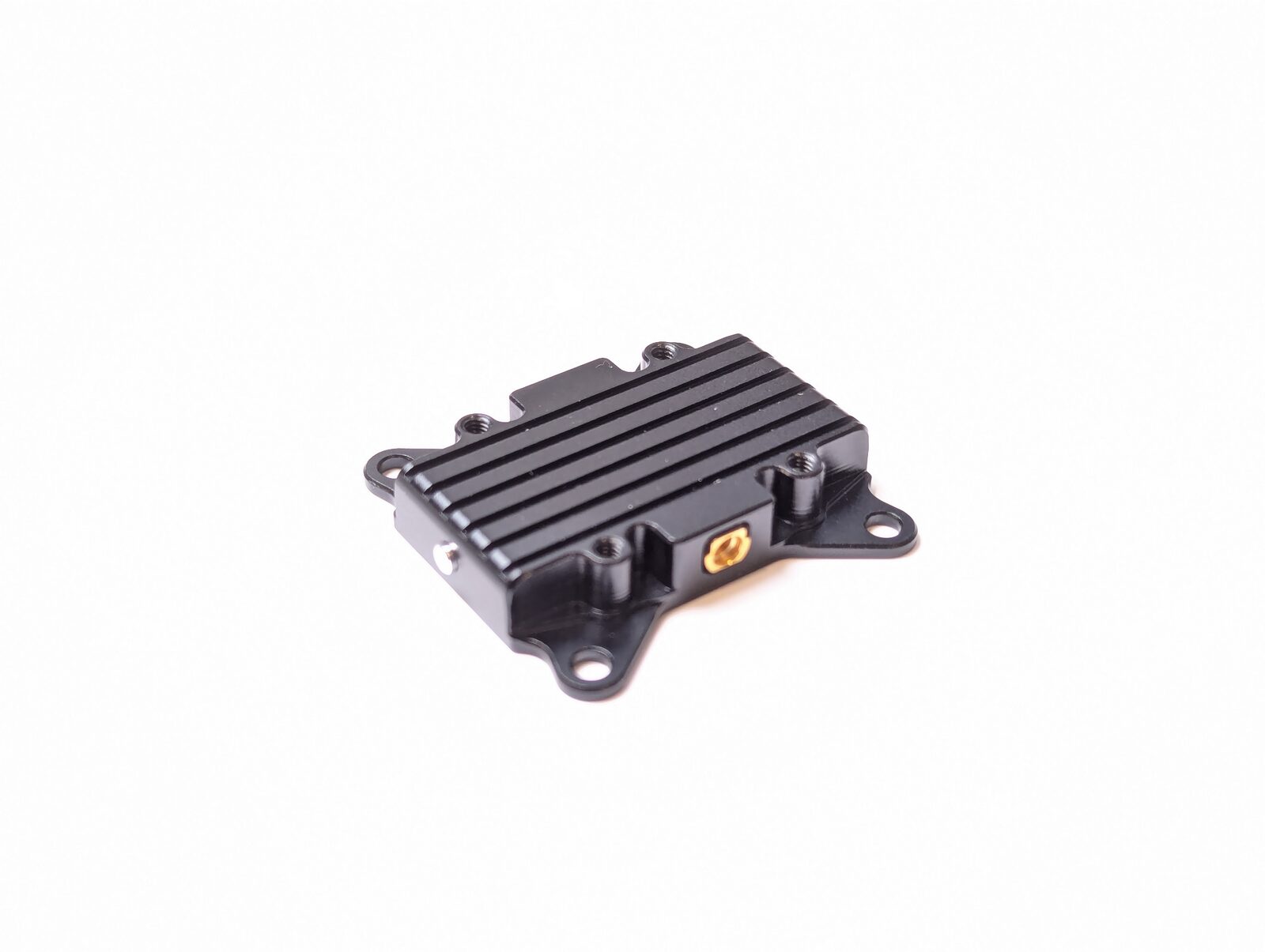
Use it when the module is buried in the airframe and you want the antenna mounted externally. The MMCX connector on the module is rated for few mating cycles — the extension also protects it from repeated plugging.
Does it work with digital FPV goggles?
No — the VT5804 is an analog transmitter (CVBS). It works with any analog 5.8 GHz receiver or goggles (including digital goggles that have an analog receiver module installed).
Related guides
- VT5805 5.8 GHz 4W Video Transmitter — User Manual
- ArduPilot — Telemetry Setup Guide
- LR900 Telemetry Radio — User Manual
- TRS — RC + Telemetry Combo User Manual
Written and maintained by the Robofusion engineering team.