MicoAir F405 V2 — Beginner ArduPilot Setup
You have soldered everything, the board powers up, and Mission Planner connects. This guide covers what happens next: turning a wired-up airframe into one that will actually fly, in the order that works.
It assumes an F405 V2 running ArduPilot (official support from 4.5.0), a quad, and a Bluejay or AM32 ESC. Most of it applies unchanged to the H743 V2 and to other ArduPilot multirotors.
Need to put ArduPilot on the board first? Firmware Flashing Guide.
Everything below is done with the propellers removed. Motors can spin during motor tests, during ESC configuration, and the moment the aircraft arms. Fit propellers only when you are finished and outdoors.
1. Set the frame type
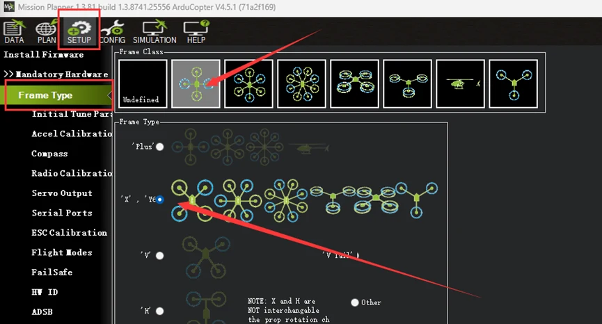
A new board does not know what it is bolted to — the frame class defaults to undefined, and nothing will arm until you tell it.
In Mission Planner, connect over USB and open Setup → Frame Type. Pick the frame class first (quad, hexa, octo…), then the layout (X, plus, H…). For most builds: Quad, then X.
2. Set the ESC protocol
ArduPilot can drive several output protocols — PWM (the default), OneShot, DShot and others. DShot300 is the right answer for a modern ESC.
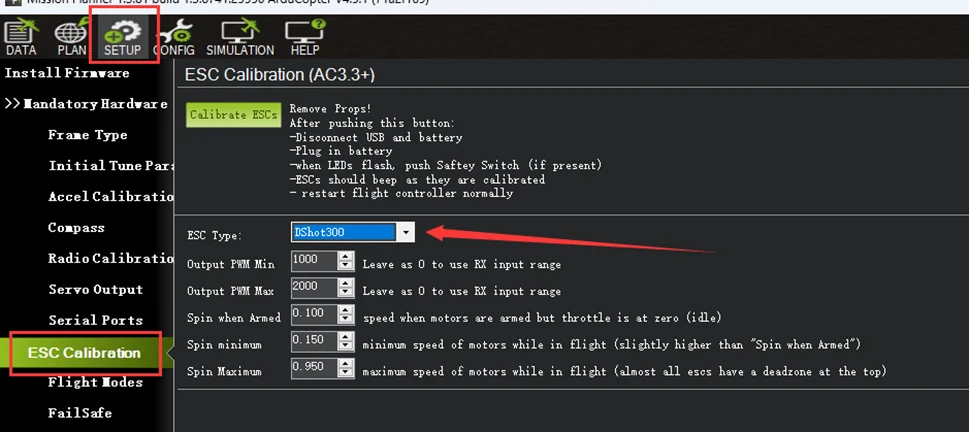
Those ESCs expect a DShot signal. Left on the default PWM protocol they never receive a valid command, so the motors do nothing at all — no spin, no beep, no error message. If you only change one thing on this page, change this one.
DShot is a digital protocol, so it also removes ESC calibration from your list of chores entirely. There is nothing to calibrate — the command is a number, not a pulse width.
3. Motor order and direction
ArduPilot assigns a specific motor number to a specific position on the frame, and expects specific directions of rotation. Your soldering does not have to match — but the configuration has to.

ArduPilot's hardware definition for the MicoAir405v2 sets the default frame type to BetaFlightX, not the standard X above. The two are not cosmetic variants — every output lands on a different corner:
| Output | Standard X | BetaFlightX |
|---|---|---|
| M1 | front right, CCW | rear right, CW |
| M2 | rear left, CCW | front right, CCW |
| M3 | front left, CW | rear left, CCW |
| M4 | rear right, CW | front left, CW |
Which one is right for you depends on how you actually soldered the motors, not on which sounds more standard. A stack whose ESC pads were laid out for Betaflight numbering usually wants BetaFlightX; a hand-wired build following an ArduPilot diagram usually wants X. Pick one, then prove it with the motor test rather than assuming — that is what the next step is for.
Check the order
With propellers off, use Mission Planner's motor test. It spins one motor at a time, labelled A, B, C, D — which correspond to motors 1, 2, 3, 4. Watch which physical motor moves for each.
If they do not match, remap them on the Servo Output page rather than resoldering: change which output each motor function is assigned to.
Check the direction
While you are testing, watch which way each motor turns. On a Quad X: motors 1 and 2 turn counter-clockwise, motors 3 and 4 turn clockwise.
To reverse one, you have two options. The crude one is swapping any two of the three motor wires. The better one is changing it in the ESC:
-
Set
SERVO_BLH_AUTO = 1andSERVO_BLH_MASK = 15(outputs 1–4), write, and reboot.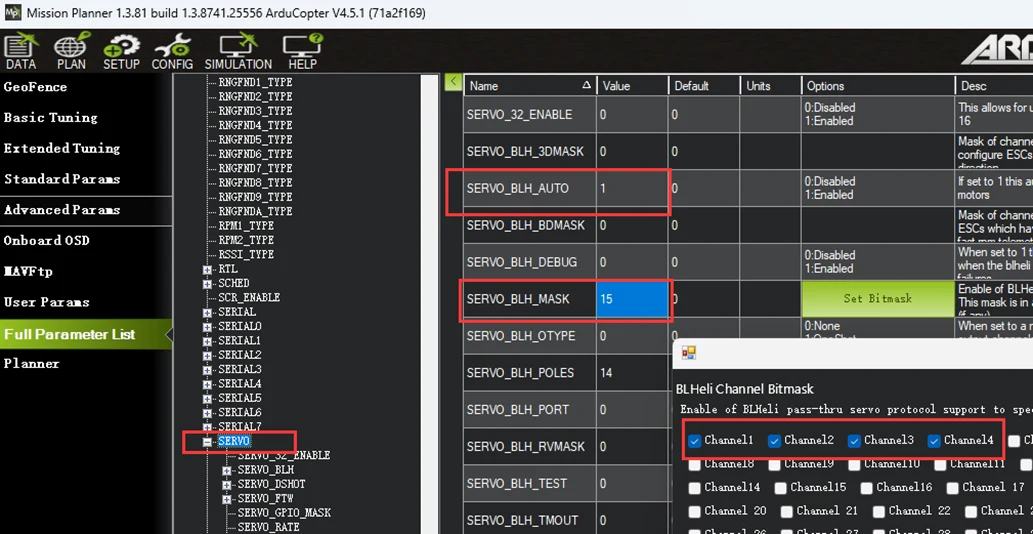
-
Open an ESC configurator and change the direction — see Configuring ESC Parameters.
Once you are done, return SERVO_BLH_AUTO and SERVO_BLH_MASK to their defaults. Leaving passthrough enabled can stop the ESCs being driven properly — and the symptom is motors that no longer respond, which looks exactly like the problem you started with.
4. Connect the receiver
SBUS
Wire the receiver's signal to the RC pad (UART6 RX). Only the signal line is needed — TX6 is unused.
SERIAL6_PROTOCOL = 23 (RCIN) is the default, so normally there is nothing to change.
ELRS or CRSF
These are bidirectional, so they need a full UART — the SBUS pad is receive-only and hardware-inverted, and will never work with them.
- Wire the receiver to UART1, crossing TX and RX.
- Set
SERIAL1_PROTOCOL = 23. - Set
SERIAL5_PROTOCOLandSERIAL6_PROTOCOLto None, so nothing else is competing for RC input.
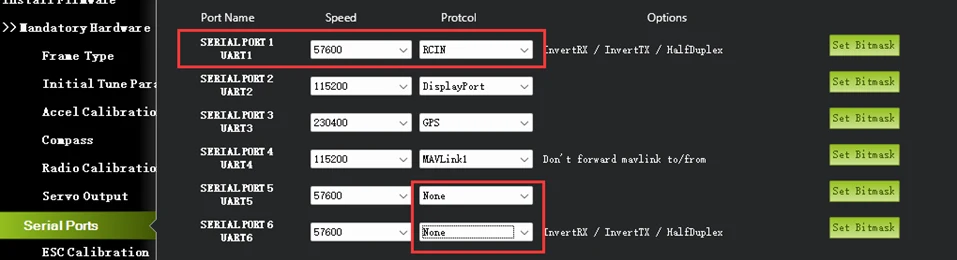
With the receiver bound and wired correctly, the channel bars in Mission Planner move when you move the sticks. Do not continue until they do.
5. Generate initial tune parameters
Recent versions of Mission Planner include an Initial Tune Parameters page, and it is the single biggest favour you can do a new aircraft. It turns two numbers into a complete starting set of PID and filter values.
Open Setup → Initial Tune Parameters and fill in:
- Airscrew size in inches — your propeller size, not the frame's. A 5-inch quad takes
5; a 7-inch takes7. - Battery cell count —
4for 4S,6for 6S. - Battery chemistry — LiPo, or Li-HV if you fly high-voltage packs.
Click Calculate Initial Parameters, then Write to FC.
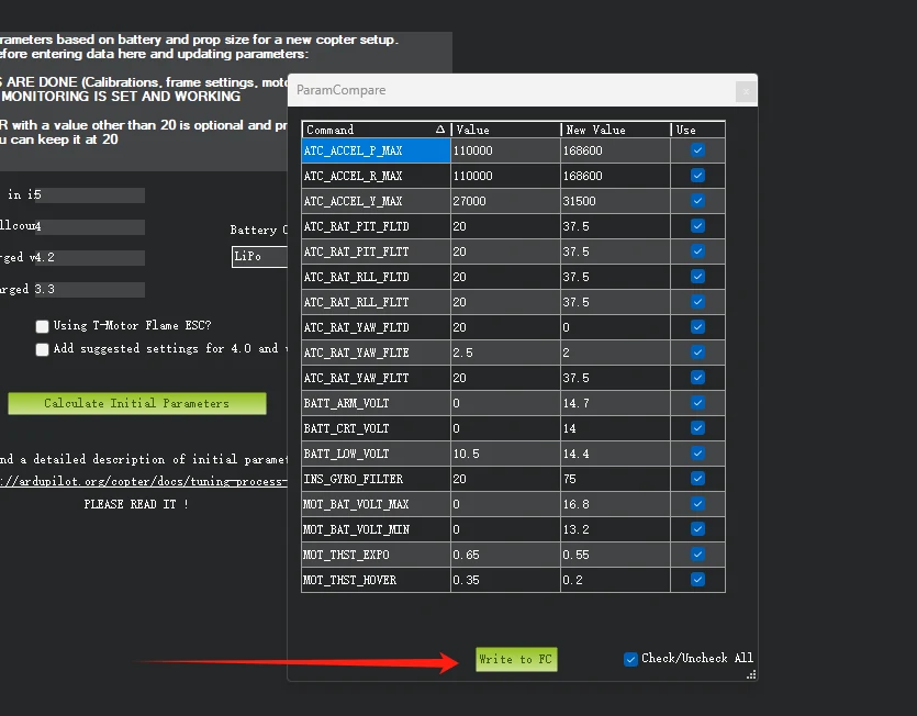
This is not a substitute for tuning. It is the difference between starting from values chosen for your airframe and starting from values chosen for nobody's.
6. Calibrate the accelerometer
Open Setup → Accel Calibration and click Calibrate Accel.
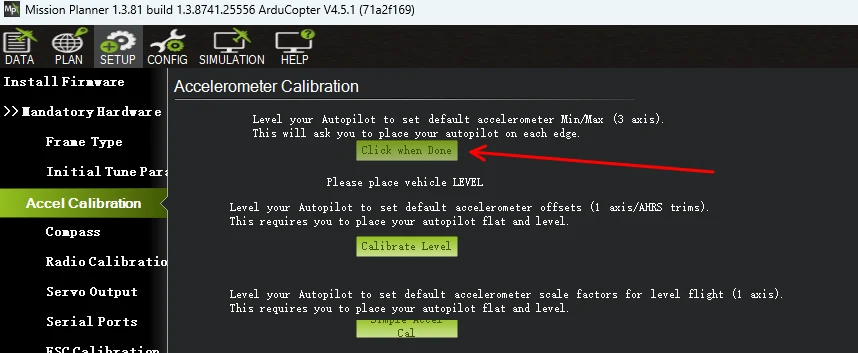
The aircraft has to be held still in six positions — level, left side down, right side down, nose down, nose up, and inverted — clicking to confirm each one.
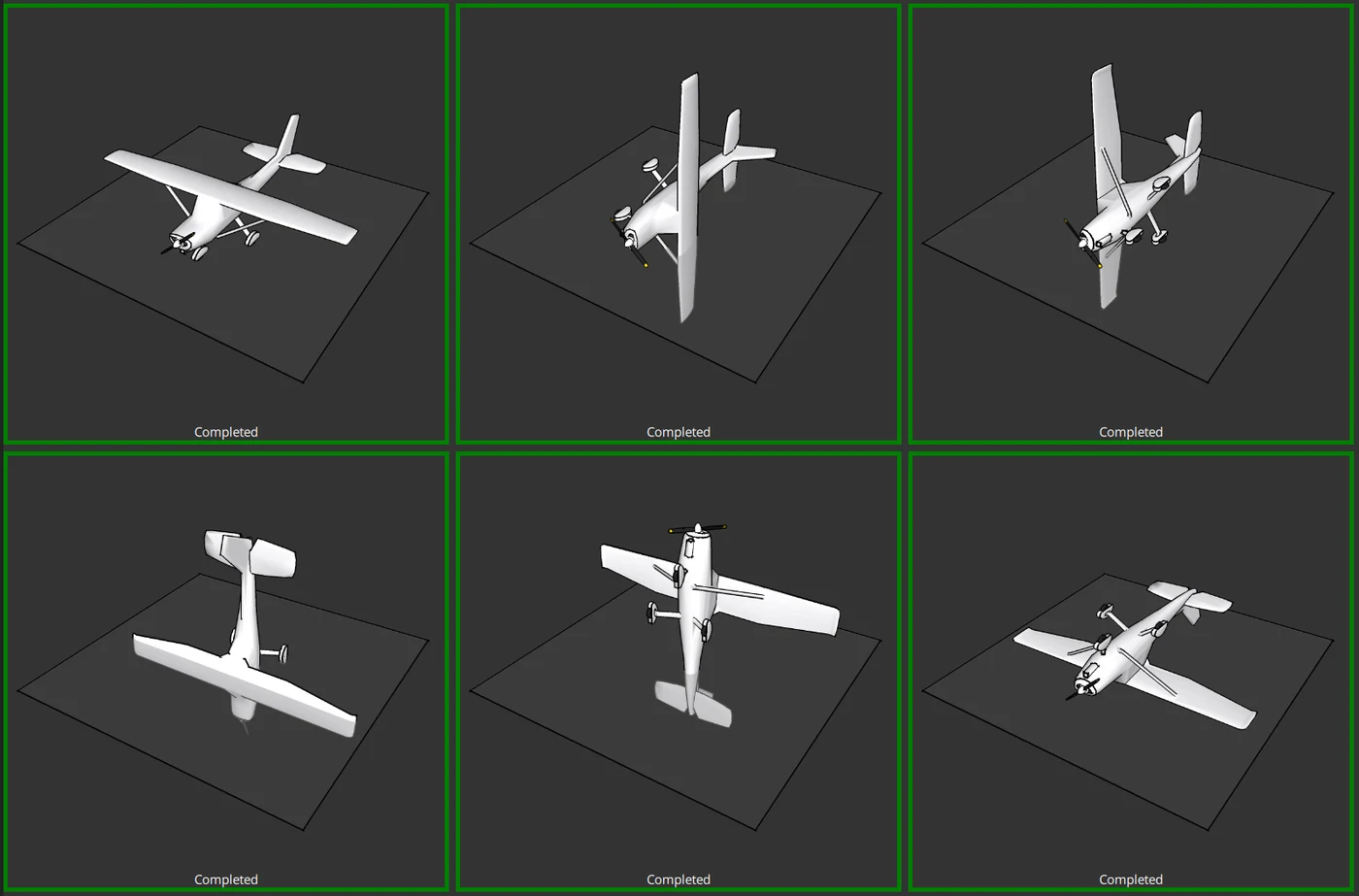
Rest it on a flat surface for each position rather than holding it in mid-air, and wait for it to settle before clicking. When it finishes you get Calibration successful.
7. Calibrate the compass
Open Setup → Compass and click Start.
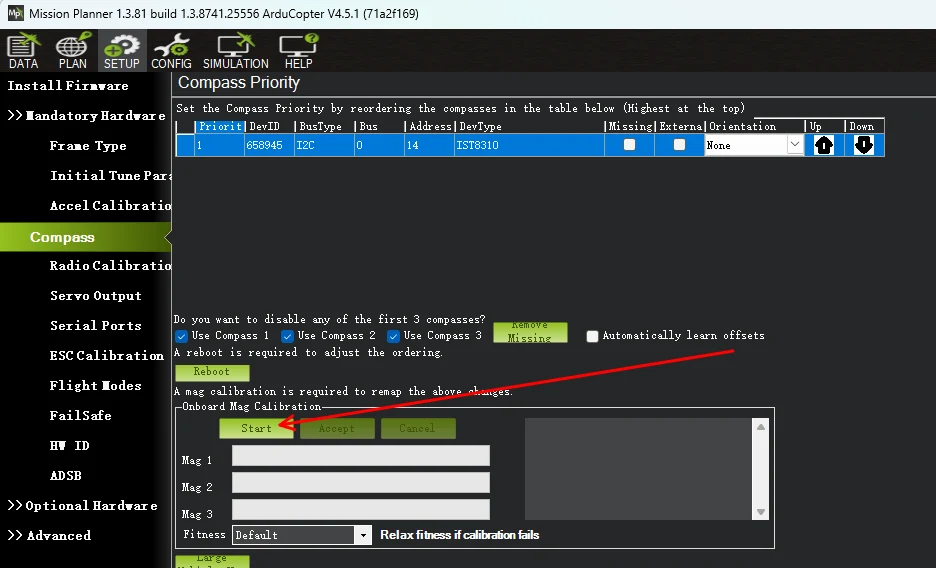
Rotate the aircraft continuously about every axis — the usual technique is drawing figure-eights in the air while turning it over — until the progress bar reaches 100% and it reports MAG_CAL_SUCCESS. Then reboot when prompted.
Do this outdoors, away from cars, steel benches, reinforced concrete and mains wiring. All of them distort the field you are trying to measure.
If clicking Start does nothing and this message appears, the firmware could not allocate memory for the calibration task. Set LOG_FILE_BUFSIZE = 8, reboot the flight controller, and calibrate again.
Getting the compass orientation right matters just as much as calibrating it — see External Compass Orientation.
8. Calibrate the radio
First make sure the transmitter is on and bound, and that Mission Planner sees the channels moving.
Check the pitch direction first
Push the pitch stick fully forward (down). The PITCH bar in Mission Planner should read its maximum.
If it reads minimum instead, reverse the channel: RC2_REVERSED = 1.
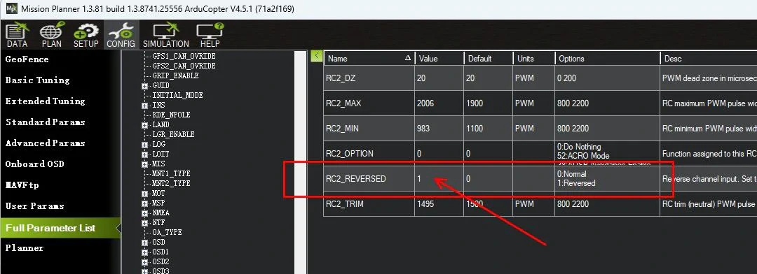
Getting this backwards means an aircraft that pitches the wrong way, which is not something to discover in the air.
Run the calibration
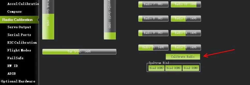
Open Setup → Radio Calibration and click Calibrate Radio. Move every stick and every switch to both extremes, several times, then finish.
9. Set flight modes
ArduPilot switches modes on channel 5 by default (FLTMODE_CH changes that). A typical three-position switch gives you three modes.
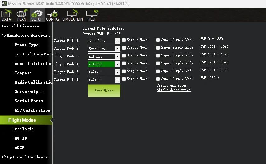
Modes worth knowing on day one:
| Mode | What it does |
|---|---|
| Stabilize | Self-levelling, manual throttle. The basic mode, and the one to take off in. |
| AltHold | Holds height; the throttle stick commands climb and descent, centred means hold. |
| Loiter | Holds position and height. Needs GPS, optical flow or another position source. |
| PosHold | Another position-holding mode, with more direct stick feel than Loiter. |
| Acro | Rate mode — no self-levelling. For pilots who want it, not for a first flight. |
A sensible first set: Stabilize, AltHold, Loiter.
10. Arming checks
ArduPilot runs a list of pre-flight checks before it will let the motors arm. Every one of them is on by default, and a first build will usually fail at least one.
Which parameter controls them depends on your firmware version, and the two are inverted:
| Firmware | Parameter | What the bitmask means | Default |
|---|---|---|---|
| 4.7 and later | ARMING_SKIPCHK | checks to skip | 0 — skip nothing |
| 4.6 and earlier | ARMING_CHECK | checks to perform | 1 — the "All" bit |
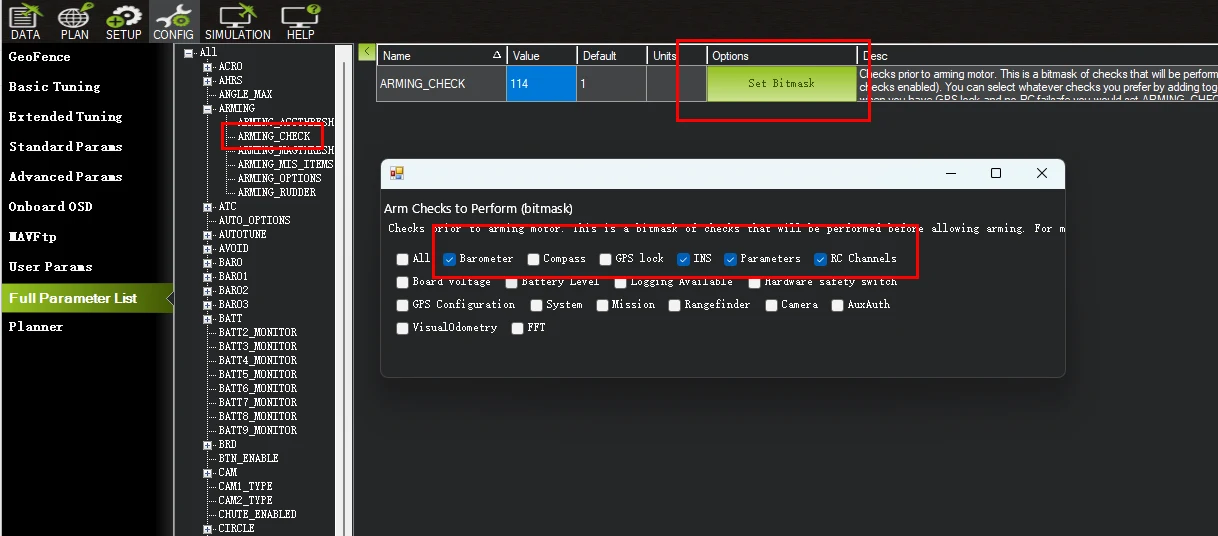
The older ARMING_CHECK parameter, shown with most checks ticked. On 4.7 and later the parameter is ARMING_SKIPCHK and a ticked box means the opposite — that check is skipped.
If you upgrade a board from 4.6 to 4.7, ArduPilot converts your old ARMING_CHECK value into the equivalent ARMING_SKIPCHK value automatically, so you should not need to redo it. But if you follow an older tutorial on 4.7 firmware and set the numbers by hand, you will disable exactly the checks you meant to keep.
It is common to reduce the checks while bench testing, and that is fine for bench testing. Put them all back before you fly. Every check in that list exists because something went wrong for somebody, and a first build is exactly the situation they are designed for. When a check refuses to pass, the fix is to address what it is complaining about — not to switch it off.
11. Arm
Default ArduPilot arming: hold the throttle stick down and to the right for three seconds. Disarm: hold it down and to the left for three seconds, with the aircraft on the ground.
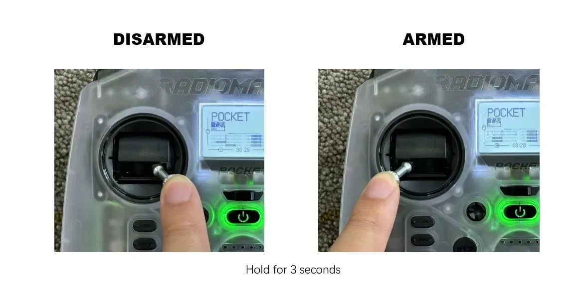
Do this first with propellers still off, indoors, and confirm the motors spin up together and respond to throttle. Only then fit propellers, go outside, and take off in Stabilize.
Easily confused points
Motor numbering is ArduPilot's, not your frame's. The pad marked 1 on the ESC and the motor ArduPilot calls 1 are unrelated until you have checked.
"X" and "BetaFlightX" are different frame types. They swap which output drives which corner, and this board defaults to the second one.
"No motors" is almost always the ESC protocol. DShot300 before anything else.
Passthrough parameters have to be put back. SERVO_BLH_AUTO and SERVO_BLH_MASK are for the duration of an ESC configuration session, not permanently.
The SBUS pad is not a UART. ELRS and CRSF need a real UART with both wires.
"Airscrew size" means the propeller. A 5-inch quad is named after its props, so the two coincide — but on anything unusual, enter the prop.
The arming-check parameter was inverted in 4.7. ARMING_CHECK listed the checks to run; ARMING_SKIPCHK lists the checks to skip. Numbers copied from an older tutorial will do the opposite of what you want.
Calibration is not tuning. Accelerometer and compass calibration make the sensors truthful; Initial Tune Parameters make the control loops sane. You need both.
Arming checks are not an obstacle. They are the part of the system that is looking out for you.
Troubleshooting
| Symptom | Where to look |
|---|---|
| Will not arm, no clear reason | Frame class still undefined; a failing arming check — read the message in Mission Planner's HUD. |
| Motors do not respond at all | ESC protocol not DShot300; flight battery not connected. |
| One motor spins the wrong way | Reverse that ESC via passthrough, then restore the passthrough parameters. |
| Motors respond to the wrong stick | Motor order — remap on the Servo Output page, do not resolder. |
| Channels do not move in Mission Planner | Receiver not bound, TX/RX not crossed on a full-UART receiver, or the port protocol is not 23. |
| Pitch responds backwards | RC2_REVERSED = 1. |
| Compass calibration will not start | LOG_FILE_BUFSIZE = 8, then reboot. |
| Heading wrong by 90/180/270° | Compass orientation, not calibration. |
Related guides
- MicoAir F405 V2 — User Manual
- Firmware Flashing Guide
- Configuring ESC Parameters
- MicoAir 4-in-1 Bluejay ESC — User Manual
- Drone GPS & Compass Guide
- External Compass Orientation
Where to buy
- MicoAir F405 V2 Flight Controller
- F405 V2 + 50A Bluejay stack — flight controller and ESC together
Written and maintained by the Robofusion engineering team.