MicoAir F405 Mini Flight Controller — User Manual
The MicoAir F405 Mini (board name: MicoAir405Mini) is the 20 × 20 mm version of MicoAir's F405 line: the same STM32F405 processor and the same feature set as the F405 V2, at 6 g on a footprint that fits 3-inch and small 5-inch frames where a 30.5 × 30.5 stack will not go.
It keeps the things people actually use — analog OSD, a DJI O3 connector, a microSD slot and six UARTs — rather than stripping them out to save space.
Where to buy
Ships from Canada with free Canada-wide shipping:
- MicoAir F405 Mini — flight controller alone, or as a stack with a Bluejay 30A 4-in-1 ESC
Specifications
| Item | Specification |
|---|---|
| MCU | STM32F405RGT6, 168 MHz, 1 MB flash |
| IMU | BMI270 |
| Barometer | DPS310 |
| OSD chip | AT7456E (analog) |
| Compass | None built-in — external via I2C |
| Logging | microSD card slot |
| Interfaces | 6× UART, 9× PWM, 1× I2C, 1× SWD, 2× ADC (voltage / current) |
| USB | Type-C |
| HD VTX connector | SH1.0-6P for DJI O3 Air Unit — pin 1 is 9 V |
| BEC | 5 V 2.5 A (receiver, GPS, optical flow) + 9 V 2.5 A (VTX, camera) |
| Battery sensing | on board, up to 6S |
| Mounting | 20 × 20 mm, Φ3.5 mm holes |
| Dimensions / weight | 30 × 30 × 8 mm / 6 g |
F405 Mini or F405 V2?
| F405 Mini | F405 V2 | |
|---|---|---|
| Mounting | 20 × 20 mm (Φ3.5) | 30.5 × 30.5 mm (Φ4) |
| Size / weight | 30 × 30 × 8 mm / 6 g | 36 × 36 × 8 mm / 9 g |
| IMU | BMI270 | BMI088 |
| Barometer | DPS310 | SPL06 |
| PWM outputs | 9 | 10 |
| BEC | 5 V 2.5 A + 9 V 2.5 A | 5 V 3 A + 9 V 3 A |
| ArduPilot target | MicoAir405Mini | MicoAir405v2 |
The real choice is size against IMU. The Mini is smaller and lighter; the V2 carries the BMI088, the industrial-grade Bosch IMU that shrugs off motor vibration better than the BMI270. On a clean, well-balanced small quad the Mini is fine; on a bigger or rougher airframe the V2's IMU earns its extra 3 g.
MicoAir405Mini and MicoAir405v2 are different boards. Firmware for one will flash and boot on the other, and then put motors, GPS and battery sensing on the wrong pins. Read the target name before you flash — see the Firmware Flashing Guide.
Pinout
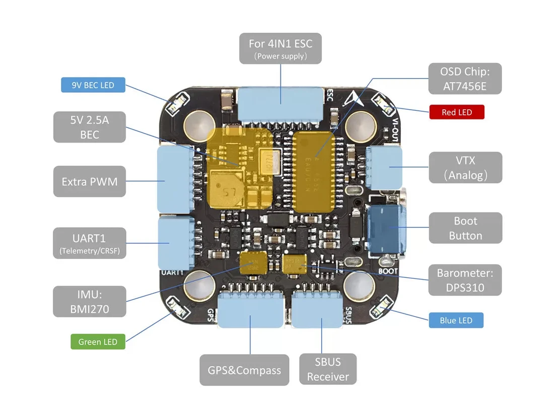
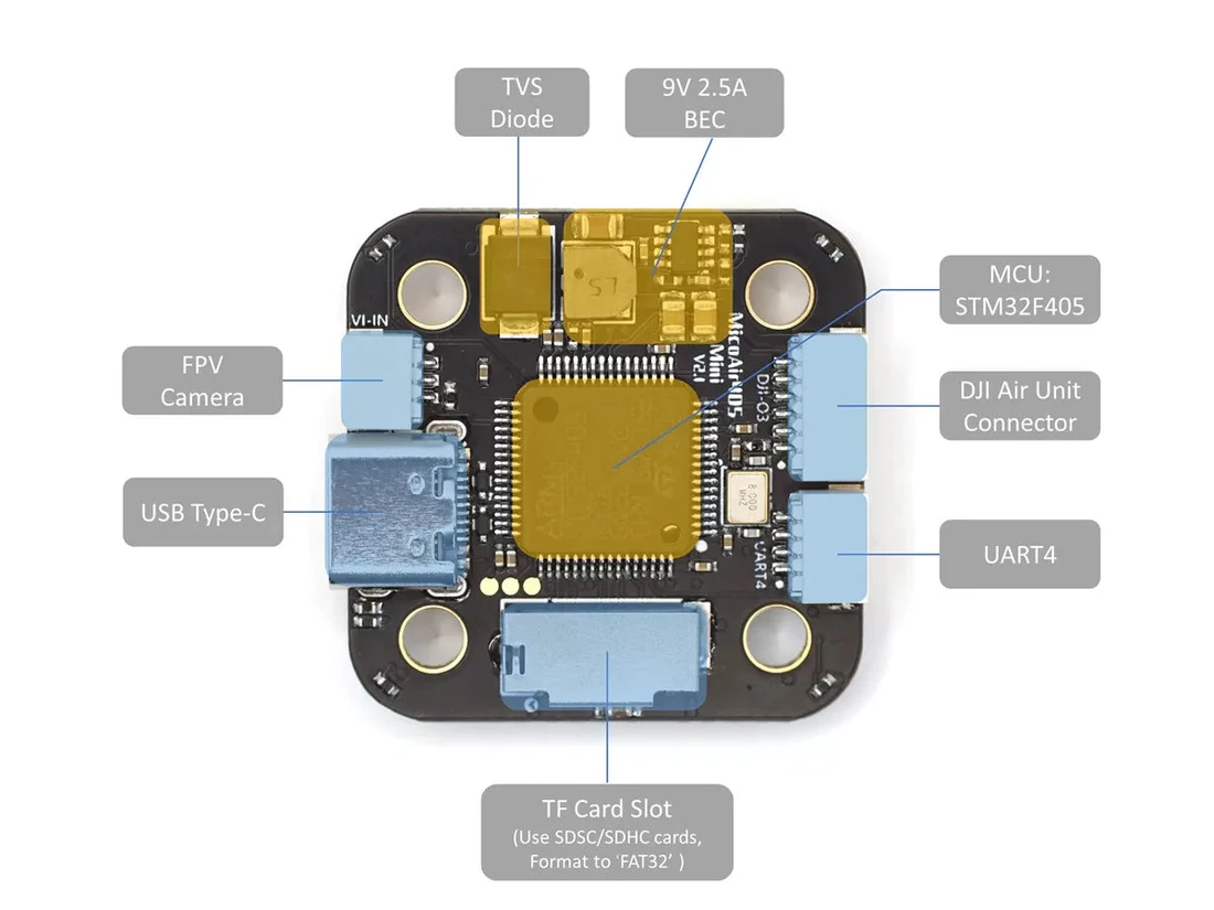
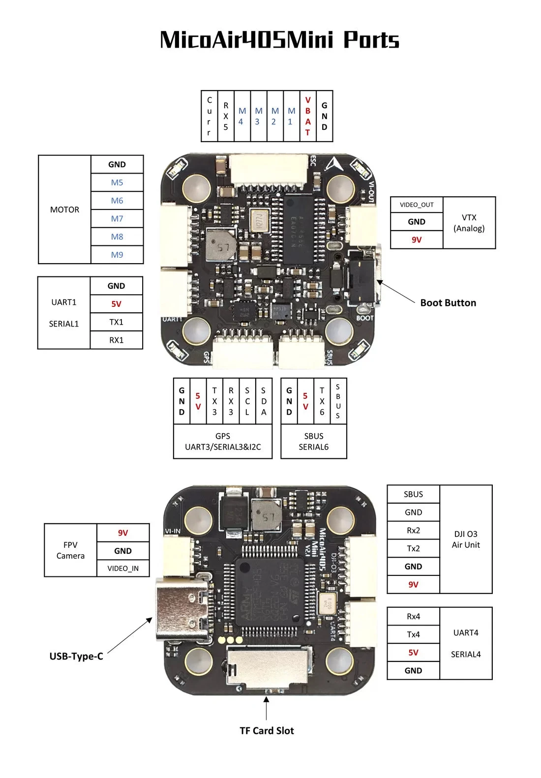
The SH1.0-6P connector carries the 9 V BEC rail for a DJI O3 Air Unit. A 5 V camera or receiver connected to that pin will be destroyed.
Worth noting if you own more than one MicoAir board: this position is 9 V here and on the F405 V2, but 12 V on the H743 V2 and the H743 AIO. The connector looks identical on all of them.
UART mapping
| Port | ArduPilot | Default function |
|---|---|---|
| USB | SERIAL0 | ground station |
| UART1 | SERIAL1 | spare (DMA) — the usual home for CRSF/ELRS |
| UART2 | SERIAL2 | DJI VTX (DMA) |
| UART3 | SERIAL3 | GPS |
| UART4 | SERIAL4 | spare (DMA) |
| UART5 | SERIAL5 | ESC telemetry |
| UART6 | SERIAL6 | RC input — RX6 inverted from the SBUS pad; no DMA on TX6 |
RC input
- SBUS — use the dedicated SBUS pad, which is hardware-inverted into RX6. Works out of the box.
- CRSF / ELRS — these are bidirectional and need a full UART: use UART1 or UART4, crossing TX and RX, set that port's
SERIALn_PROTOCOL = 23, and changeSERIAL6_PROTOCOLto something other than 23. - PPM — not supported.
That pad runs through a hardware inverter and is receive-only. SBUS is a one-way inverted signal, which is exactly what it is built for. CRSF and ELRS need to talk back, and there is no path for that — no parameter change makes it work.
PWM outputs and DShot
Nine outputs. 1–8 support DShot; 1–4 additionally support bi-directional DShot (RPM telemetry for gyro filtering).
Outputs are grouped by timer, and every output in a group must run a compatible protocol:
| Group | Outputs |
|---|---|
| 1 | 1, 2, 5, 6 |
| 2 | 3, 4 |
| 3 | 7, 8 |
| 4 | 9 |
The grouping does not follow the numbering: outputs 1, 2, 5 and 6 share a timer while 3 and 4 share another, so a four-motor quad spans two groups.
ArduPilot's hardware definition for the MicoAir405Mini sets the default frame type to BetaFlightX, not standard X — and the two put every output on a different corner:
| Output | Standard X | BetaFlightX |
|---|---|---|
| M1 | front right, CCW | rear right, CW |
| M2 | rear left, CCW | front right, CCW |
| M3 | front left, CW | rear left, CCW |
| M4 | rear right, CW | front left, CW |
Choose whichever matches how you actually wired the motors, then confirm it with the motor test before fitting propellers.
Set the ESC protocol to DShot300 before anything else — a Bluejay or AM32 ESC will not respond at all to the default PWM output, silently and without an error.
OSD
The board carries an AT7456E analog OSD chip. On ArduPilot, OSD_TYPE = 1 (MAX7456 driver) — which is already the default on this board.
Pair it with an analog video transmitter such as the VT5804 or VT5805, or use the SH1.0-6P connector for a DJI O3.
Battery monitoring
On-board voltage sensing up to 6S; current comes from the 4-in-1 ESC through the ESC connector.
| Parameter | Value |
|---|---|
BATT_VOLT_PIN | 10 |
BATT_CURR_PIN | 11 |
BATT_VOLT_MULT | 21.2 |
BATT_AMP_PERVLT | 40.2 |
BATT_AMP_PERVLT = 40.2 implies a sensor of about 24.9 mV/A, which does not correspond to the Bluejay ESC (12.75 mV/A, about 78 A/V) that ships in the stack bundle — nor to the AM32 boards. Whichever ESC you fit, calibrate: compare the mAh the flight controller reports with what your charger puts back in, and scale the parameter by that ratio.
Compass
There is no compass on the board. For GPS flight, add an external one on the SDA / SCL pads — usually the magnetometer inside a GPS module, mounted on a mast away from the power wiring.
Set its orientation by hand: with no internal compass to compare against, ArduPilot's automatic detection cannot work. See External Compass Orientation.
Firmware
| Firmware | Target |
|---|---|
| ArduPilot | MicoAir405Mini |
| INAV | MicoAir405Mini builds |
| Betaflight | MicoAir405Mini builds |
PX4 is not supported on F405 hardware — use the H743 V2 or NxtPX4 V2 for that.
Flashing, DFU mode and file formats: Firmware Flashing Guide.
Easily confused points
MicoAir405Mini is not MicoAir405v2. Different boards, different pin maps, one character apart in a list.
Pin 1 of the video connector is 9 V here, 12 V on the H743 boards. Same connector, different rail.
The SBUS pad is not a UART. Inverted and receive-only.
Timer groups do not follow output numbers. 1, 2, 5, 6 together; 3 and 4 together.
DShot is outputs 1–8; bi-directional DShot is only 1–4.
"X" and "BetaFlightX" are different frame types, and this board defaults to the second.
No compass on board — and therefore no compass orientation auto-detection either.
Troubleshooting
| Symptom | Where to look |
|---|---|
| Motors do nothing | ESC protocol not DShot300; flight battery not connected. |
| Motors on the wrong corners | Frame type — standard X vs BetaFlightX. Confirm with the motor test. |
| ELRS receiver not detected | Wired to the SBUS pad instead of a full UART, or the port protocol is not 23. |
| Compass not detected | I2C wiring on SDA/SCL. |
| Heading off by a constant angle | Compass orientation — set it manually on this board. |
| Current reading far too low | BATT_AMP_PERVLT left at the board default. |
| Video transmitter destroyed on first power-up | Pin 1 is 9 V, not 5 V. |
Related guides
- MicoAir F405 V2 Flight Controller — User Manual — the 30.5 × 30.5 sibling
- F405 V2 — Beginner ArduPilot Setup Guide — the setup order applies here too
- MicoAir 4-in-1 Bluejay ESC — User Manual
- Firmware Flashing Guide
- External Compass Orientation
Written and maintained by the Robofusion engineering team.