MicoAir H743 V2 Flight Controller — User Manual
The MicoAir H743 V2 (board name: MicoAir743v2) is a high-performance 30.5×30.5 flight controller built around the STM32H743 processor with dual IMUs (BMI088 + BMI270), a built-in Bluetooth telemetry module, and native support for all four major open-source firmwares: ArduPilot, PX4, INAV, and Betaflight. It is the flagship flight controller in the Robofusion lineup and the board we recommend for most ArduPilot builds.
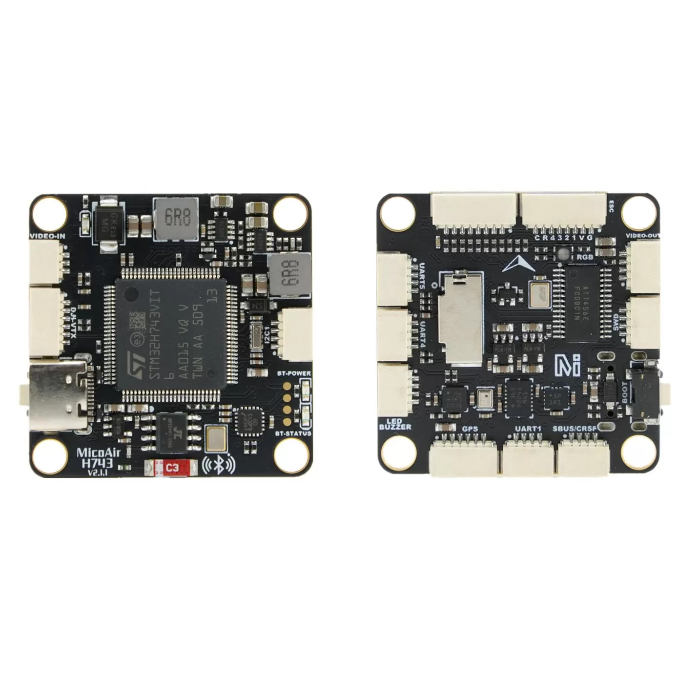
Where to buy
- Robofusion store (ships from Canada — free Canada-wide shipping): MicoAir H743 V2 Flight Controller — available as FC only, or as a stack with a 55 A / 70 A AM32 4-in-1 ESC
A flight controller (FC) is the drone's brain: it reads motion sensors (the IMU — gyroscope + accelerometer) hundreds of times per second, figures out which way the aircraft is tilting, and adjusts each motor's speed to keep it stable. Everything else connects to it — GPS, receiver, video transmitter, telemetry radio. Two spec letters matter most when choosing one: F4 vs H7 describes the processor generation (H7 is roughly 3× faster with 2× the memory — headroom for logging, scripting, and future firmware versions), and the IMU model determines how clean the motion data is. The H743 V2 pairs the fast processor with two independent IMUs, so the firmware can cross-check them and keep flying even if one misbehaves.
H743 V2, F405 V2, or NxtPX4 V2 — which one?
| H743 V2 | F405 V2 | NxtPX4 V2 | |
|---|---|---|---|
| Processor | STM32H743, 480 MHz | STM32F405, 168 MHz | STM32H743, 480 MHz |
| IMU | BMI088 + BMI270 (dual) | BMI088 | BMI088 × 2 (dual) |
| Compass | Built-in QMC5883L | External (via I2C) | External (via I2C) |
| Firmware | ArduPilot / PX4 / INAV / Betaflight | ArduPilot / INAV | PX4 (native) / ArduPilot |
| UARTs / PWM | 8 / 11 | 6 / 10 | 7 / 8 |
| Bluetooth telemetry | Built-in | — | — |
| Mounting | 30.5 × 30.5 mm | 30.5 × 30.5 mm | 20 × 20 mm |
| Best for | Full-featured ArduPilot/PX4 builds, do-it-all choice | Budget long-range ArduPilot/INAV builds | Small research & VIO drones, PX4 labs |
Specifications
| Item | Specification |
|---|---|
| MCU | STM32H743VIT6, 480 MHz, 2 MB flash |
| IMU | BMI088 + BMI270 (dual, independent) |
| Barometer | SPL06 |
| Compass | QMC5883L (built-in) |
| OSD chip | AT7456E (analog OSD) |
| Logging | MicroSD card slot |
| Interfaces | 8× UART, 11× PWM, 1× I2C, 1× SWD, 2× ADC (voltage / current) |
| USB | Type-C |
| HD VTX connector | SH1.0-6P for DJI O3 / O4 Air Unit and other HD systems |
| BEC | 5 V 3 A (receiver, GPS, optical flow…) + 12 V 3 A (VTX, camera) |
| Bluetooth | Built-in module on UART8, 115200 baud |
| Battery input | 2–6S LiPo (6–27 V), on-board voltage sensing |
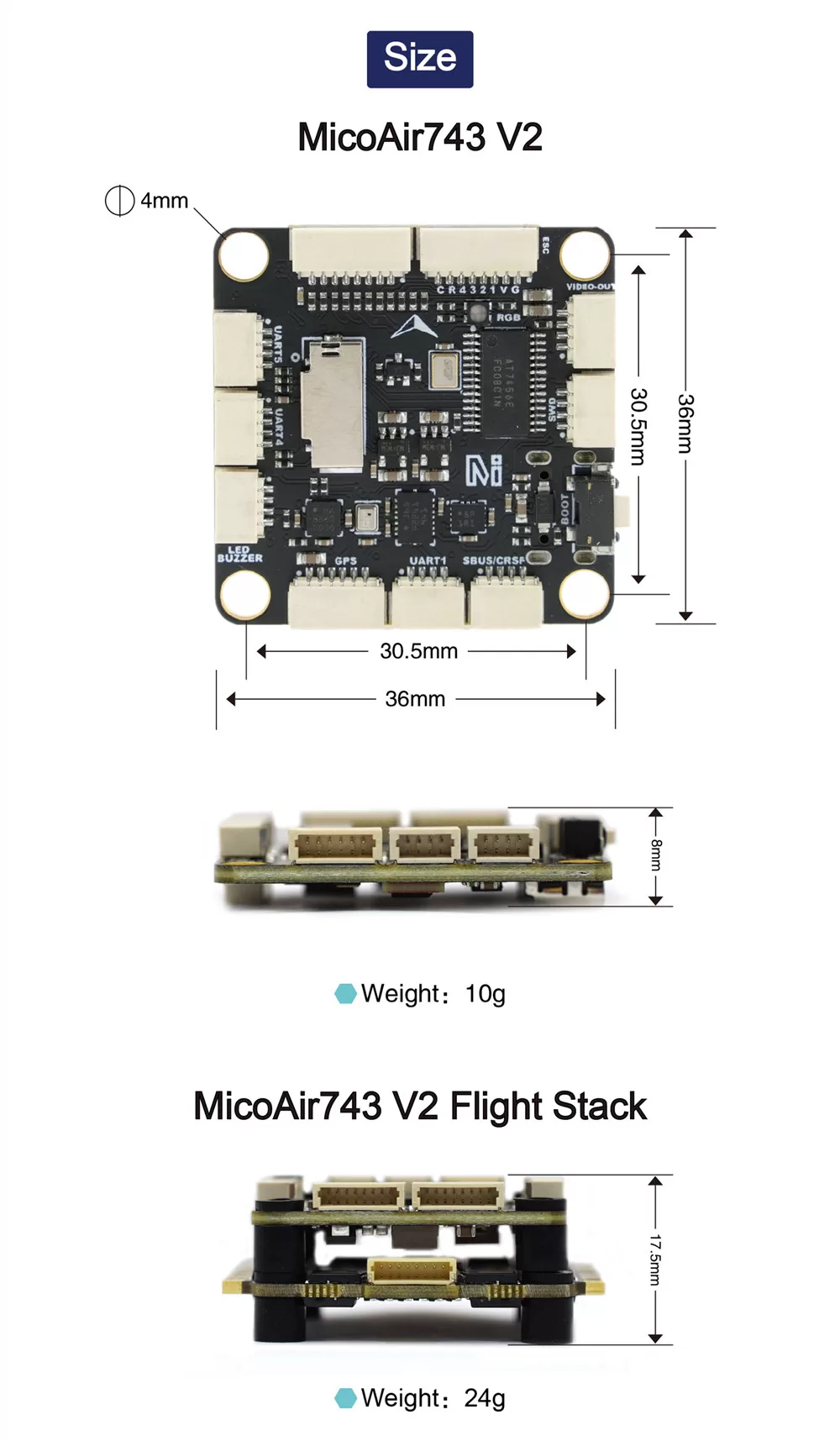
| Mounting | 30.5 × 30.5 mm, Φ4 mm holes |
| Dimensions / weight | 36 × 36 × 8 mm / 10 g |
Pinout
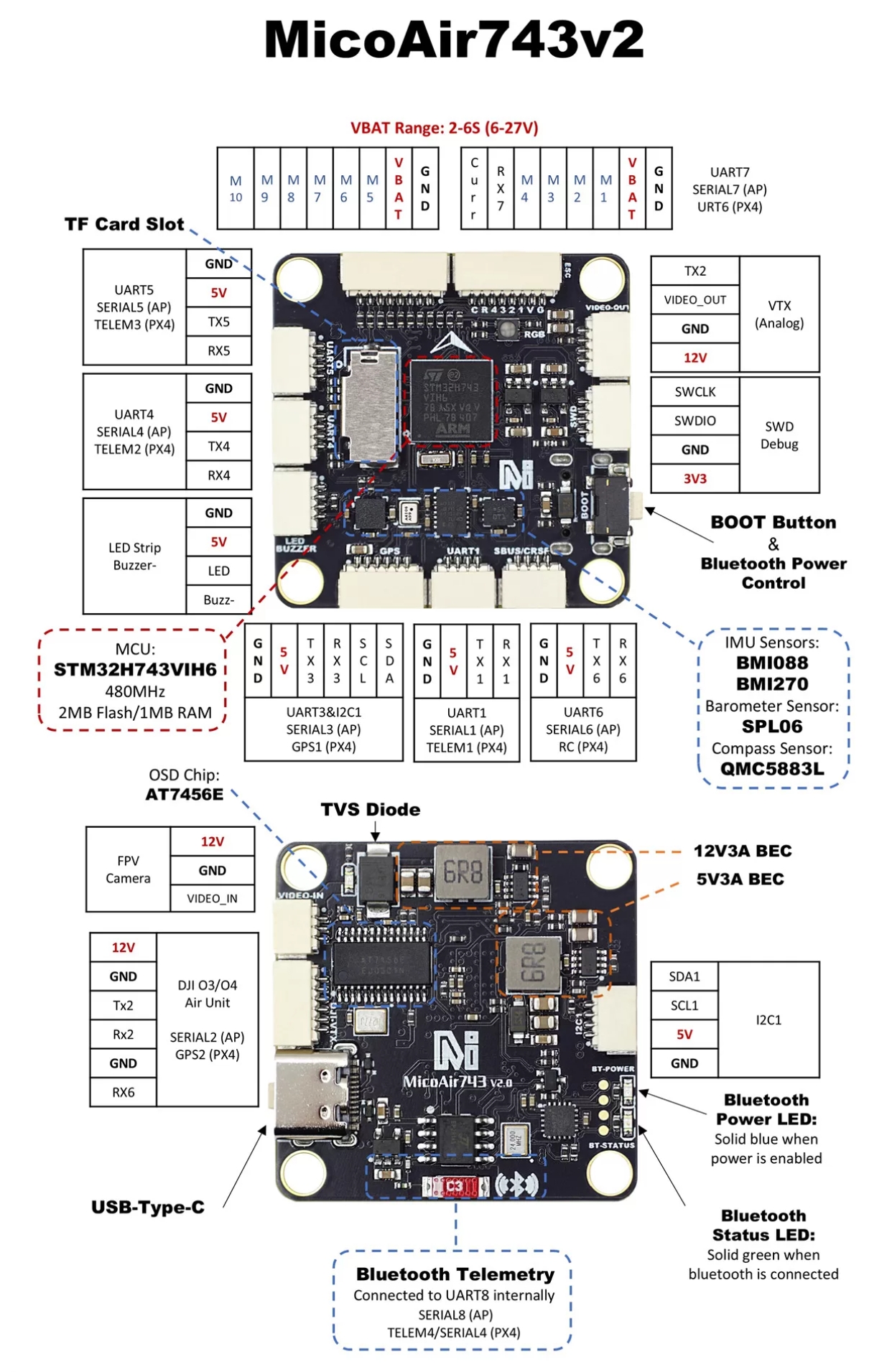
Connector pin list
Pins are listed in the order printed on MicoAir's port diagram. Before plugging anything in, match the first and last pin against the silkscreen next to the connector — the diagram shows which end is which, a text table cannot.
| Connector | Pins | Port (ArduPilot / PX4) | Notes |
|---|---|---|---|
| ESC (main, 8-pin) | Curr · RX7 · M4 · M3 · M2 · M1 · VBAT · GND | RX7 = SERIAL7 / URT6 | ESC telemetry on RX7; current sensor on Curr |
| Motors 5–10 (8-pin) | M10 · M9 · M8 · M7 · M6 · M5 · VBAT · GND | — | second 4-in-1 ESC or servos |
| GPS | GND · 5V · TX3 · RX3 · SCL · SDA | UART3 = SERIAL3 / GPS1, I2C1 | GPS plus external compass |
| UART1 | GND · 5V · TX1 · RX1 | SERIAL1 / TELEM1 | telemetry radio |
| SBUS/CRSF (UART6) | GND · 5V · TX6 · RX6 | SERIAL6 / RC | receiver |
| UART4 | GND · 5V · TX4 · RX4 | SERIAL4 / TELEM2 | |
| UART5 | GND · 5V · TX5 · RX5 | SERIAL5 / TELEM3 | |
| LED strip / buzzer | GND · 5V · LED · Buzz- | — | |
| I2C1 | SDA1 · SCL1 · 5V · GND | I2C1 | external compass or sensors |
| DJI O3/O4 (HD VTX, 6-pin) | 12V · GND · TX2 · RX2 · GND · RX6 | UART2 = SERIAL2 / GPS2 | 12 V on this connector; RX6 carries the goggles' RC link |
| Analog VTX | TX2 · VIDEO_OUT · GND · 12V | — | 12 V supply |
| FPV camera | 12V · GND · VIDEO_IN | — | 12 V supply — not for 5 V cameras |
| SWD debug | SWCLK · SWDIO · GND · 3V3 | — | recovery and debugging only |
Also on the board: USB-C, the BOOT button (also switches the Bluetooth module's power), a microSD slot, and the on-board Bluetooth telemetry wired internally to UART8 (SERIAL8 on ArduPilot, TELEM4 on PX4). Its blue LED is on when Bluetooth is powered and the green LED is on when a device is connected. BECs: 12 V 3 A and 5 V 3 A.
UART mapping
| Port | ArduPilot | PX4 | Default function |
|---|---|---|---|
| USB | SERIAL0 | ttyACM0 | GCS connection |
| UART1 | SERIAL1 | TELEM1 | MAVLink2 telemetry |
| UART2 | SERIAL2 | GPS2 | DisplayPort (HD VTX OSD) |
| UART3 | SERIAL3 | GPS1 | GPS |
| UART4 | SERIAL4 | TELEM2 | MAVLink2 (second radio / companion) |
| UART5 | SERIAL5 | TELEM3 | Spare (user) |
| UART6 | SERIAL6 | RC | RC receiver input |
| UART7 | SERIAL7 | URT6 | ESC telemetry (RX only) |
| UART8 | SERIAL8 | TELEM4 | Built-in Bluetooth |
All UARTs are DMA-enabled, so any of them can run high-rate protocols without loading the CPU.
A UART is simply a two-wire serial port (TX = transmit, RX = receive). Every peripheral — GPS, receiver, telemetry radio, VTX — occupies one. Eight UARTs is the practical difference between "plug everything in" and "choose which two accessories you can live without" on cheaper boards.
RC input
UART6 (RX6/TX6) is the default RC port and works with all ArduPilot-supported protocols:
- SBUS / DSM / SRXL — connect to RX6
- CRSF / ELRS — connect both RX6 and TX6 (telemetry comes back automatically)
- FPort — connect TX6
- SRXL2 — connect TX6 and set
SERIAL6_OPTIONS = 4 - PPM is not supported on this board
OSD and HD VTX
Two OSD paths work simultaneously:
- Analog OSD — the onboard AT7456E chip (
OSD_TYPE = 1), used with analog VTX modules like the VT5804 / VT5805. PX4 does not currently drive the analog OSD — this path is for ArduPilot, INAV and Betaflight. - DisplayPort (HD) OSD — on the SH1.0-6P HD VTX connector (
OSD_TYPE2 = 5), carried on UART2, for DJI O3/O4 and similar HD systems
Pin 1 of the SH1.0-6P connector carries the 12 V BEC rail for the video system. Never wire a 5 V peripheral to it.
PWM outputs and DShot
11 PWM outputs; channels 1–8 also support bi-directional DShot (ArduPilot/Betaflight; PX4 and INAV do not support BDShot on this board yet). Outputs are grouped — every output in a group must run the same protocol:
| Group | Outputs |
|---|---|
| 1 | 1, 2, 3, 4 |
| 2 | 5, 6 |
| 3 | 7, 8, 11 |
| 4 | 9, 10 |
PWM 11 doubles as the LED pin; if it is configured for serial LEDs, outputs 7 and 8 can only be used as serial LED outputs too. Whenever you change an output protocol, a PWM frequency or the serial-LED setting, check the whole group rather than the single output you were aiming at.
Which protocol to choose: plain PWM ESCs get a standard PWM protocol. For DShot ESCs, DShot300 is the sensible default — it is the balance point between bandwidth and reliability, and going faster buys very little on a normal quad. Bi-directional DShot needs support in both the flight controller firmware and the ESC firmware.
Remove the propellers before any motor test. Only after you have confirmed motor numbering, direction of rotation and failsafe behaviour should props go back on for a low-risk ground test.
Classic PWM sends motor commands as an analog pulse width — it works, but needs calibration and picks up noise. DShot sends the same command as a digital number, so there is nothing to calibrate and no drift. Bi-directional DShot additionally lets each ESC report motor RPM back to the FC, which enables RPM-based gyro filtering — noticeably smoother flight on ArduPilot and Betaflight.
Battery monitoring
Voltage sensing is built in (up to 6S); current sensing uses the signal from your 4-in-1 ESC via the ESC connector. Default ArduPilot parameters:
| Parameter | Value |
|---|---|
BATT_MONITOR | 4 |
BATT_VOLT_PIN | 10 |
BATT_CURR_PIN | 11 |
BATT_VOLT_MULT | 21.12 |
BATT_AMP_PERVLT | 40.2 |
After the first battery connection, verify the reported voltage against a battery checker and fine-tune BATT_VOLT_MULT if needed.
Compass
A QMC5883L compass is built in. In practice, most builders run an external compass on the GPS mast (connected via the SDA/SCL pads) and disable the internal one — the internal compass sits close to power wiring and picks up magnetic interference from motor current.
Bluetooth telemetry
The built-in Bluetooth module is wired to UART8 (115200 baud) and broadcasts as MicoAir743v2-xxxxxx — no pairing code needed. Connect from a phone GCS (QGroundControl on Android is the documented path) for wireless parameter tuning without plugging in USB. For flying range, use a proper telemetry radio like the LR900 — Bluetooth is a bench-and-field-setup convenience, not a flight link.
Turning Bluetooth on
The module has a power state of its own, and it is not necessarily on when the board is. This catches people out: they scan, find nothing, and conclude the module is faulty.
- Power the board normally and wait at least 3 seconds.
- Look for the blue Bluetooth power LED.
- If it is off, hold the BOOT button for about 2 seconds to switch Bluetooth on.
Holding BOOT again switches it back off, and the state is remembered across power cycles — so a board that was switched off last session comes back switched off.
Two LEDs report the module's state: the blue one means Bluetooth is powered, and a green one lights solid once a ground station has actually connected.
Connecting from QGroundControl on Android
- Application Settings → Comm Links → Add, and set the type to Bluetooth.
- Tap Scan and pick the device named
MicoAir743v2-xxxxx. - Select the new link and tap Connect — the green LED on the board goes solid.
- Return to the main view; parameters load in roughly 3–5 seconds.
Nothing found when scanning? Check the blue LED is lit, move the phone closer, confirm Android has granted QGroundControl Bluetooth and nearby-devices permissions, make sure UART8 has not been reassigned to something else, and delete any stale pairing entry on the phone before scanning again.
Firmware
| Firmware | Support | Target / notes |
|---|---|---|
| ArduPilot | Official from 4.6.0 | Target MicoAir743v2 — stable builds on firmware.ardupilot.org |
| PX4 | Official from 1.16.0 | Build target micoair_h743-v2_default |
| INAV | Official from 8.0.0 | Target MICOAIR743V2 |
| Betaflight | Manufacturer builds | micoair/MicoAir743v2 on GitHub |
| Skybrush | Supported | ArduPilot-derived firmware for drone light shows |
ArduPilot's board list contains several similarly named MicoAir boards — MicoAir743, MicoAir743-Lite and the MicoAir743 AIO variants are all different hardware. Flashing a near-miss target is the classic way to end up with a board that boots but has the wrong pin mapping: motors on the wrong outputs, a GPS port that never sees data, battery readings that make no sense. Check the target name character by character before you flash.
First-time flashing (DFU)
- Disconnect USB and battery.
- Hold the BOOT button, keep holding it, and plug in USB-C.
- Release once the computer has enumerated the DFU device.
- Flash the
arduXXXX_with_bl.hexfile with your DFU tool (or Mission Planner → Load custom firmware, or MicoConfigurator, which flashes straight from Chrome or Edge — Windows needs the DFU driver installed). - From then on, update normally over USB with
.apjfiles from any ArduPilot ground station — no button needed.
A board in DFU mode does not appear as a COM port the way it does with normal firmware, and its status LEDs stay dark. It shows up as a DFU device instead. Neither is a sign of a problem.
Easily confused points
MicoAir743v2 is not MicoAir743, MicoAir743-Lite or MicoAir743 AIO. Four different boards with four different pin maps and four nearly identical names. This is the single most common way to brick an afternoon.
.hex vs .apj. The _with_bl.hex file contains the bootloader and the firmware, and is what you flash over DFU on a blank or bricked board. An .apj file is firmware only, flashed by a ground station through the bootloader that is already on the board. Use the hex once; use .apj forever after.
The BOOT button does two unrelated jobs. Held while plugging in USB, it enters DFU mode for flashing. Held for ~2 seconds while the board is already running, it toggles the Bluetooth module. Same button, completely different outcomes.
Pin 1 of the HD VTX connector is 12 V, not 5 V. Wiring a 5 V camera or receiver to it destroys the peripheral, and possibly the flight controller with it.
DShot and bi-directional DShot are not the same feature. Plain DShot sends commands to the ESC. Bi-directional DShot also reads RPM back, which is what enables RPM-based filtering — and it needs matching support at both ends.
Outputs share timer groups, not just a connector. Changing output 7 to a different protocol can constrain outputs 8 and 11, because they run off the same timer. The groups are listed above.
The built-in compass is rarely the one you want to fly. It is on the board, centimetres from the power wiring. Almost every serious build uses an external compass on a GPS mast and disables the internal one.
FAQ
Which firmware should a beginner pick?
If you want GPS missions, autonomous flight and the biggest tuning community, choose ArduPilot. Pick INAV if you fly fixed-wing FPV, Betaflight for pure acro/racing quads, PX4 if your workflow depends on its ecosystem (offboard control, research tooling).
Does it work with both analog and digital (HD) FPV?
Yes, simultaneously if you like: analog VTX via the onboard OSD chip and video pads, HD systems (DJI O3/O4, etc.) via the dedicated HD VTX connector with DisplayPort OSD.
Why are two IMUs better than one?
The firmware runs both continuously and compares them. If one drifts from vibration, temperature, or damage, the other keeps the aircraft flying — and having two different sensor models (BMI088 + BMI270) means they don't share the same failure modes.
What ESC should I pair with it?
Any standard 4-in-1 ESC with a 30.5×30.5 mount. The matching option is the MicoAir 55 A or 70 A AM32 ESC — both available as a stack bundle on the product page.
Related guides
- MicoAir H743 AIO — User Manual — the same processor with the ESC built in
- F405 V2 Flight Controller — User Manual
- NxtPX4 V2 Flight Controller — User Manual
- ArduPilot — Telemetry Setup Guide
- VT5804 5.8 GHz 2.5W Video Transmitter — User Manual
Written and maintained by the Robofusion engineering team.