MicoAir 4-in-1 AM32 ESC — User Manual
The AM32 ESCs are the 32-bit half of MicoAir's 4-in-1 line: more current, more headroom and more configurability than the 8-bit Bluejay boards, aimed at larger and longer-range aircraft.
Two models, both running AM32 firmware at 48 kHz PWM with DShot300/600 support.
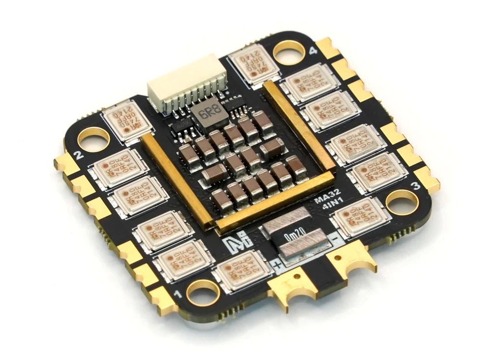
55A or 70A?
| 55A | 70A | |
|---|---|---|
| Max continuous current | 55 A × 4 | 70 A × 4 |
| Battery | 2–6S | 2–6S |
| MOSFETs | 40 V, 0.75 mΩ | 40 V, 0.95 mΩ, metal package |
| Current-sensor output | 12.75 mV/A | 10.2 mV/A |
| Mounting | 30.5 × 30.5 (Φ4) + 20 × 20 (Φ3) | 30.5 × 30.5 mm (Φ4) |
| Board size | 43.5 × 41 mm | 43.5 × 42.5 mm |
| Weight | 14 g | 14.5 g |
| Suggested airframe | 3.5–10 inch | 5–12 inch |
Shared by both: AM32 firmware (AM32_F4A_4IN1_F421_2.19), 48 kHz PWM, PWM / DShot300 / DShot600, and an SH1.0-8P connector.
Because sustained current is limited by heat, not by resistance alone. The 55A's MOSFETs have the lower RDS(on) at 0.75 mΩ, but the 70A's are in a metal package that moves heat off the die far more effectively. More heat out means more current in, even though each amp costs slightly more loss. Resistance tells you how much heat is produced; packaging tells you how much can be removed.
Choosing in practice:
- 55A — the more flexible board. It covers 3.5 to 10 inch, and it is the only one of the two with both hole patterns, so it fits 20 × 20 mm stacks as well as 30.5 × 30.5.
- 70A — for 5 to 12 inch aircraft, heavy lifters and long-range builds where sustained current matters more than a few grams or millimetres.
The continuous ratings assume good heat dissipation. Neither should be run in a sealed compartment. An ESC with nowhere to put its heat will get hot, derate, and eventually fail — and the failure will be during the part of the flight that was drawing the most current.
Where to buy
Ships from Canada with free Canada-wide shipping:
- MicoAir 70A 4-in-1 AM32 ESC
- H743 V2 + AM32 flight stack — the H743 V2 with either the 55A or the 70A
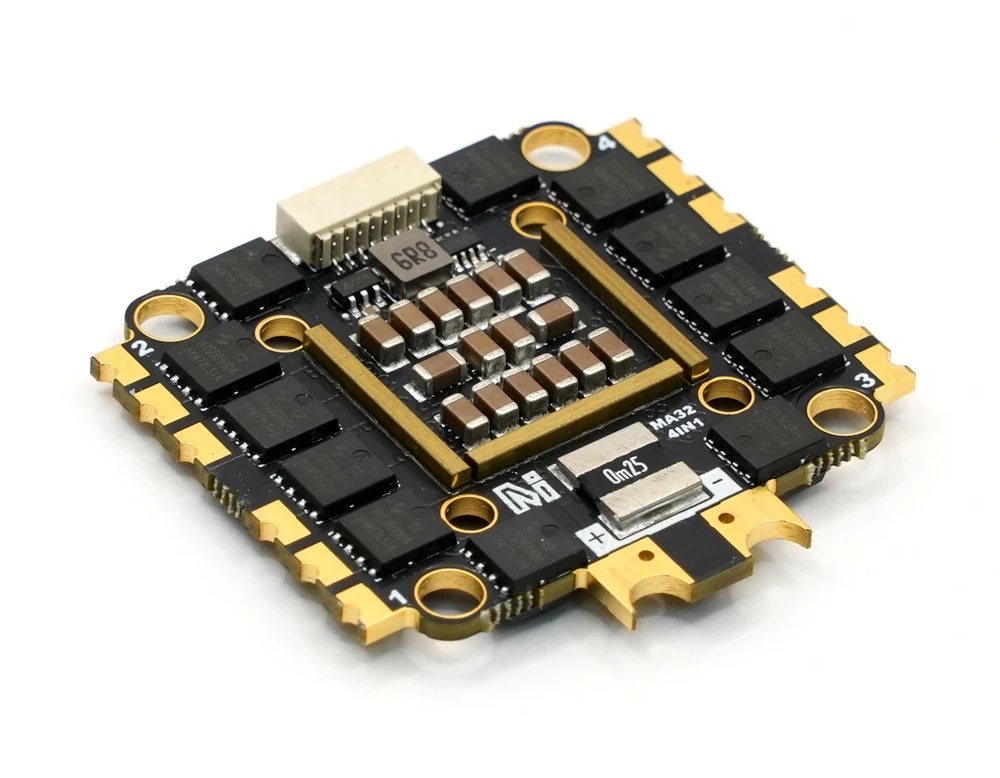
Connector pinout
Both models use the same SH1.0-8P connector, with the same pin order as the Bluejay boards:

| Pin | Function |
|---|---|
| Curr | Current-sensor output — 12.75 mV/A on the 55A, 10.2 mV/A on the 70A |
| NC | Not connected |
| M4 – M1 | Motor signal inputs from the flight controller's outputs |
| VBAT | Raw battery voltage out — typically used to power the flight controller. A 6S pack puts about 22.2 V here |
| GND | Power ground |
It feeds the flight controller's own regulator. A receiver, GPS or camera connected to this pin will be destroyed.
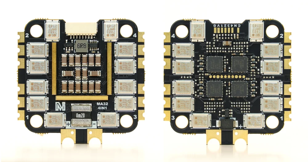
Installing it

- Battery to the ESC — solder the leads or an XT60 to the
+and−pads. Reversed polarity destroys the board instantly. - Fit the capacitor across the same pads. It absorbs the voltage spikes that switching motors put on the power rail; without it those spikes reach the flight controller and the video system.
- Motors to the ESC — three wires each, to pads 1–4. Direction is set in software later, so wire order does not matter yet.
- Ribbon to the flight controller using the SH1.0-8P cable.
- Mount on soft grommets, to keep motor vibration out of the flight controller's gyro.
Remove the propellers before wiring, testing motors, checking direction or changing ESC settings.
Flight controller setup
Set the protocol to DShot300
AM32 accepts PWM, DShot300 and DShot600. DShot300 is the recommended setting — the balance point between bandwidth and reliability.
If the flight controller is left on a protocol the ESC does not expect, the motors will not respond at all on arming or motor test, with no error reported.
Set the motor KV
This one is specific to AM32 and easy to miss.
The firmware ships with a motor KV value of 2220, which suits a typical freestyle motor. That value feeds the ESC's timing behaviour — so if you have fitted a large low-KV motor or a small very-high-KV motor, the default no longer describes your hardware and the motor may not reach the speed you expect.
Set it to match the motors you actually fitted, in an AM32 configurator: Configuring ESC Parameters.
Set the current-sensor scaling
The two models differ, so check which one you have:
| ESC | Sensor output | ArduPilot BATT_AMP_PERVLT |
|---|---|---|
| 55A | 12.75 mV/A | ≈ 78 |
| 70A | 10.2 mV/A | ≈ 98 |
ArduPilot's BATT_AMP_PERVLT is expressed in amps per volt, so the figure is 1 ÷ (mV/A ÷ 1000).
MicoAir's F405 V2 and H743 V2 ship with BATT_AMP_PERVLT = 40.2, which implies a sensor of about 24.9 mV/A — that is neither 12.75 nor 10.2. Leave the default in place and the reported current will be substantially lower than reality, which makes consumed-mAh and any current-based failsafe wrong in the direction that lets you fly on further than you should.
Treat the calculated figure as a starting point, then calibrate:
- Fly a pack down, or run a known load.
- Compare the mAh the flight controller reported with the mAh your charger puts back in.
- Scale
BATT_AMP_PERVLTby that ratio. - Repeat once to confirm.
AM32, Bluejay and the rest
| Firmware | Hardware | Notes |
|---|---|---|
| BLHeli_S | 8-bit | Long-standing stock firmware for this class. No bidirectional DShot. |
| Bluejay | 8-bit | Open-source, same hardware and configurator as BLHeli_S. Adds 48 kHz PWM and bidirectional DShot. |
| BLHeli_32 | 32-bit | More capable, closed source, no longer developed. |
| AM32 | 32-bit | Open-source firmware for 32-bit ESCs — what these boards run. More headroom and more settings, including motor KV. |
The practical split: Bluejay on our 8-bit boards covers small and mid-size quads very well; AM32 is the 32-bit path, with the extra current handling and the extra configurability that larger motors benefit from.
Easily confused points
The two models have different current sensors. 12.75 mV/A on the 55A, 10.2 mV/A on the 70A — and neither matches the flight controller's default. This is the single most likely thing to get wrong.
Lower resistance does not mean higher rating. Packaging and heat dissipation decide sustained current.
The KV setting is not decorative. AM32's default assumes a 2220 KV motor.
"Continuous current" assumes airflow. Not in a sealed compartment.
"No motors" is a protocol setting. DShot300 first.
A 4-in-1 is four ESCs. One channel can fail alone — if exactly one motor misbehaves, suspect that channel.
VBAT is not a 5 V rail.
Troubleshooting
| Symptom | Where to look |
|---|---|
| No motors respond at all | ESC protocol not DShot300; ribbon not seated; no battery (USB does not power the ESC). |
| One motor does not spin | That channel — motor solder joints, the motor itself, or that one ESC. |
| Motors spin the wrong way | Reverse it in the ESC configurator, not by swapping wires. |
| Motor will not reach expected speed | Motor KV setting still at the 2220 default while a very different motor is fitted. |
| Current reads far too low | BATT_AMP_PERVLT left at the board default — see the scaling table above. |
| ESC gets very hot | Undersized for the build, or mounted with no airflow. |
| Noisy gyro, bars in the video | Missing capacitor, or the stack mounted hard to the frame instead of on grommets. |
Related guides
- How to Configure Open-Source ESC Parameters — motor direction, KV, and firmware updates
- MicoAir 4-in-1 Bluejay ESC — User Manual — the 8-bit boards
- H743 V2 Flight Controller — User Manual
- F405 V2 — Beginner ArduPilot Setup Guide
Written and maintained by the Robofusion engineering team.