MicoAir LR900 915 MHz Telemetry Radio — User Manual
The LR900 is a family of long-range telemetry radios that gives a drone a wireless serial cable to the ground. Plug one into a flight controller's serial port, plug the other into a laptop's USB port, and Mission Planner or QGroundControl sees the aircraft exactly as if it were tethered — live attitude, GPS position, battery, mission upload and parameter tuning, at ranges a USB cable obviously cannot reach.
It is the right module if you fly ArduPilot or PX4 beyond the reach of a USB lead, if you want to tune parameters without landing, or if you need a data pipe to carry RTK correction data from a base station out to one or more aircraft. It operates in the 890–915 MHz band using LoRa spread-spectrum modulation with optional FHSS frequency hopping, which is what buys it range and interference resistance.
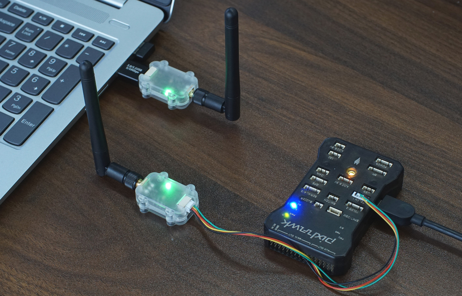
LoRa is a spread-spectrum modulation scheme: it spreads a small amount of data across a wide slice of spectrum so the receiver can dig the signal out from below the noise floor. That is why a 500 mW LoRa link reaches much further than a 500 mW conventional link — you trade data rate for range.
FHSS (frequency-hopping spread spectrum) means the pair continuously retunes to different frequencies in a shared, synchronised pattern. A jammer or a neighbour's radio sitting on one frequency only corrupts the hops that land on it, so the link degrades gracefully instead of dropping.
Where to buy
- Robofusion store (ships from Canada — free Canada-wide shipping): LR900-P — 1 W flagship (pair) · LR900-F — 500 mW (pair) · LR900-A — budget (pair)
- Amazon (US): LR900-F on Amazon
Which LR900 model should I buy?
| Model | Max Tx power | Enclosure | USB-to-serial chip | FHSS support | Max serial packet |
|---|---|---|---|---|---|
| LR900-A | 22 dBm (160 mW) | none (bare board) | CH340 | No | 4 KB |
| LR900-F | 27 dBm (500 mW) | yes | CP2102 | Yes | 8 KB |
| LR900-P | 30 dBm (1000 mW) | yes | CP2102 | Yes | 8 KB |
All three models pair freely with one another. Link range follows the weaker end: an LR900-P on the ground talking to an LR900-A in the air behaves like an LR900-A link, because the aircraft's 160 mW signal is what the ground station has to hear.
A practical way to choose:
- LR900-A — bench work, short-range testing, budget builds, or as a cheap second pair for RTK corrections over a short baseline.
- LR900-F — the default choice for most aircraft. 500 mW, cased, FHSS-capable, 8 g.
- LR900-P — long-range and marginal-link work. Because transmit power costs weight and current on the aircraft but neither on the ground, a very common pairing is LR900-P on the ground, LR900-F in the air.
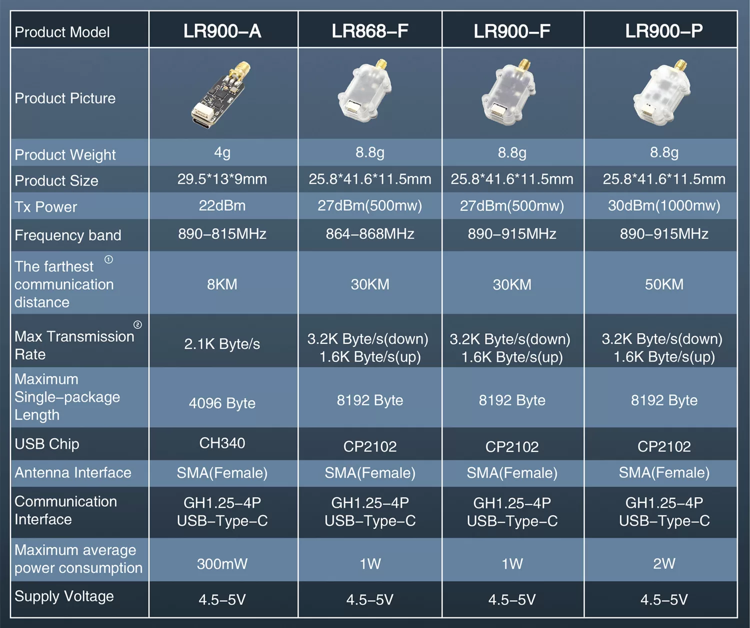
You may see an LR868-F in older MicoAir materials and in the comparison chart above. It is the same 500 mW radio tuned for the EU 868 MHz band. We don't sell it — in North America the 915 MHz models are the right choice — and the current LR900 lineup is the A, F and P.
Specifications
| Parameter | Value |
|---|---|
| Operating band | 890–915 MHz |
| Transmit power | 1000 mW (LR900-P); 500 mW (LR900-F); 160 mW (LR900-A) |
| Max transparent throughput | 2.1 KB/s; 3.2 KB/s (FHSS downlink; not supported on LR900-A) |
| Max serial single-packet length | 4 KB (LR900-A); 8 KB (LR900-F/P) |
| Communication interface | LVTTL (3.3 V) serial; USB Type-C |
| Serial baud rate | Default 57600 |
| Antenna connector | SMA (external thread, centre socket) |
| Supply voltage | 4.5–5 V |
| Max average power consumption | 2 W (LR900-P); 1 W (LR900-F); 300 mW (LR900-A) |
| Weight | 8 g |
LVTTL (3.3 V) simply means the serial port swings between 0 V and 3.3 V, which is what every modern flight controller uses. It is not RS-232 and not 5 V logic — do not wire this port to a PC serial port or to a 5 V UART without a level shifter.
The LR900 hardware tunes across 890–915 MHz, which is wider than any single region's licence-free allocation. You are responsible for operating only on frequencies and power levels permitted where you fly. In the U.S. and Canada the commonly used licence-free band is 902–928 MHz; leave the radio in its default automatic frequency mode unless you have checked that the channel you are about to select manually is legal for you.
Avoid running a 915 MHz RC control link and a 915 MHz LR900 telemetry link on the same airframe. Two transmitters a few centimetres apart in the same band will desensitise each other, and the failure mode is a control link that degrades exactly when you are far away. Pair a 2.4 GHz RC link with LR900 telemetry, or move telemetry to the 2.4 GHz LR24 if your RC link is on 915 MHz.
Dimensions
LR900-F/P dimensions (mm):
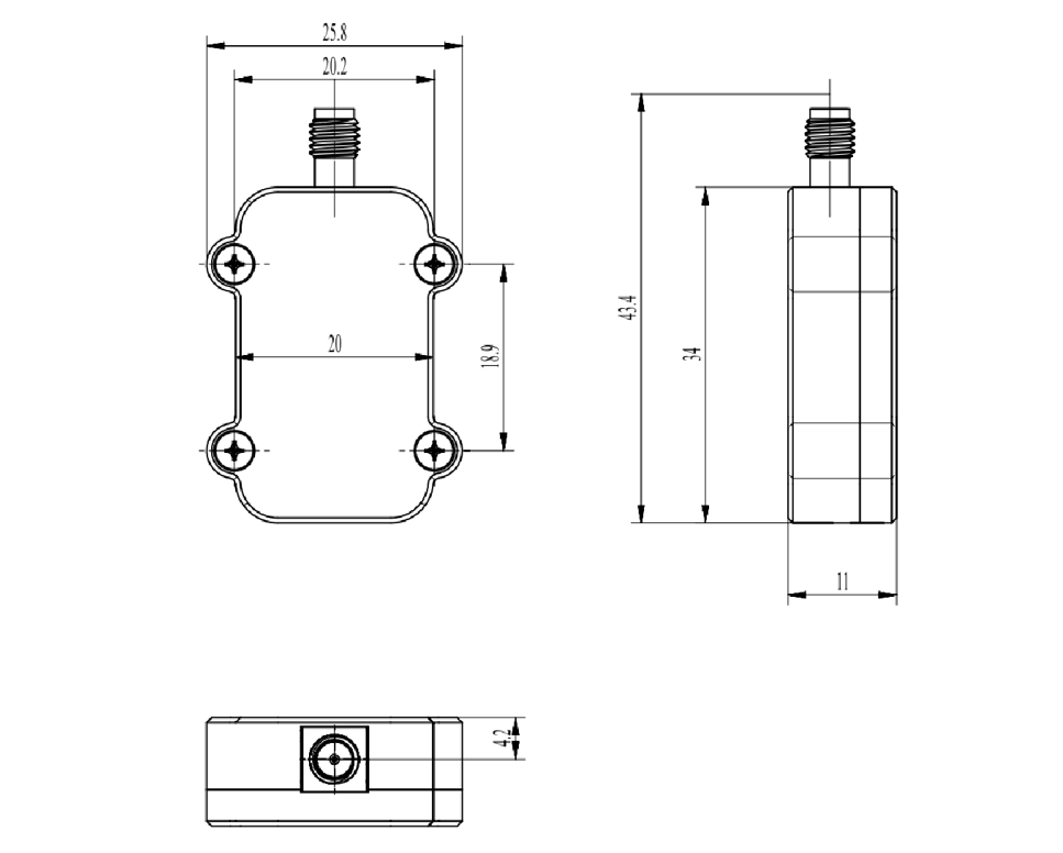
- Weight: 8 g
- 3D model (STP)
Interfaces and pinout
The LR900 has two external connectors:
- A 3.3 V TTL serial port on a GH1.25-4P connector — this is what goes to the flight controller.
- A USB Type-C port, used to connect the radio to a computer. The matching USB-to-serial driver must be installed on the computer. This port cannot be used to connect the radio to a flight controller.
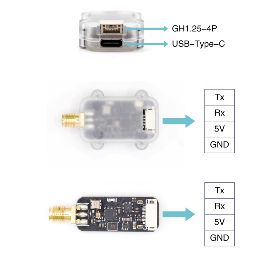
| Pin | Connect to |
|---|---|
| Tx | Flight controller serial Rx |
| Rx | Flight controller serial Tx |
| 5V | Flight controller 5 V |
| GND | Flight controller GND |
Tx and Rx must cross. Tx means "this device transmits", Rx means "this device receives" — so one device's transmit line has to land on the other's receive line. Wiring Tx to Tx is the single most common reason a new telemetry install shows no data at all, with both LEDs looking perfectly healthy. Many pre-made cables already cross the pair inside the loom; if yours does, do not cross it a second time.
Configuration software and drivers
Radio parameters are set with the MicoAssistant configuration tool, which is also available as a browser-based configurator at micoair.com/assistant — no installation needed. Connect the radio to the computer over USB-C, open the tool, read the parameters, change what you need and write them back.
USB-to-serial drivers (needed before the radio will appear as a COM port on Windows):
- CH340 driver download — for the LR900-A
- CP2102 Driver Installation Guide (Windows) — for the LR900-F/P
What do the LED codes mean?
The LR900 has a single green LED that reports link status:
| LED | Meaning |
|---|---|
| Blinking at 1 Hz | No link — the other radio is off, out of range, or configured with different parameters |
| Solid on | Linked and passing data normally |
A solid LED means the two radios are talking. It does not mean the flight controller is talking — if the LEDs are solid on both ends but the ground station shows nothing, the problem is downstream of the radio: Tx/Rx not crossed, or a serial baud rate mismatch with the flight controller.
How do the radios pair?
There is no bind button and no pairing procedure. Two LR900 modules whose parameters match connect automatically at power-up, and every unit ships with identical factory defaults — so a fresh pair links itself the first time you power both ends.
If you need several pairs of radios working at the same time in the same place, give each pair its own module address (see below). Radios with different addresses ignore each other.
Parameter reference
Work mode
Three modes: duplex, broadcast-transmit and broadcast-receive. Default is duplex.
- Duplex — both radios send and receive. This is the only mode usable for flight-controller telemetry, because the ground station has to be able to send commands and parameter writes back up to the aircraft.
- Broadcast-transmit / broadcast-receive — a one-way link. One transmitter, any number of receivers. This is the mode used for RTK corrections: the base station's radio broadcasts, and every aircraft's radio listens.
Data rate (transparent transmission speed)
Three rate modes, symmetric in each direction:
| Setting | Over-the-air rate |
|---|---|
| Low | 0.4 KB/s |
| Medium | 1.1 KB/s |
| High (default) | 2.1 KB/s |
For flight-controller telemetry, only high is recommended — MAVLink streams are not shy about bandwidth, and a slower air rate shows up as laggy, stuttering telemetry. For a low-rate non-MAVLink serial link, a slower setting trades throughput for range. Both radios must be on the same data rate or they will not link.
Transmit power
Three settings — low / medium / high, default high. The wattage each one corresponds to depends on the model (the maximum is 160 mW on the LR900-A, 500 mW on the F and 1000 mW on the P). Unlike the pairing-related parameters, this one does not have to match: the two ends can run different transmit powers, which is why a high-power ground radio paired with a lower-power air radio is a normal arrangement. Turning it down is worth doing for bench testing, where full power into a radio a metre away is simply wasted current.
Frequency mode
- LR900-A — manual / auto
- LR900-F/P — manual / auto / FHSS-GROUND / FHSS-AIR
Default is auto, where the operating frequency is chosen automatically. In manual mode you pick the channel yourself with the frequency-point parameter.
FHSS is the recommended mode for flight-controller telemetry on the F and P. Set the radio connected to the flight controller to FHSS-AIR, and the radio connected to the computer to FHSS-GROUND. The two settings are not interchangeable. In FHSS mode the downlink (flight controller → computer) runs faster, up to 3.2 KB/s, which is where the extra headroom for high-rate telemetry comes from. The LR900-A does not support FHSS.
Frequency point (channel)
Takes effect only in manual frequency mode. Values 0–25 correspond to 890–915 MHz, i.e. one step per MHz.
Module address
Default 1000; range 1–30000. Only two modules with the same address can talk to each other. Give each pair of radios its own address when running several links at once.
Serial baud rate
Baud rate of the GH1.25 serial port — this must match the flight controller's serial port setting. Supports 9600 / 19200 / 38400 / 57600 / 115200; default 57600.
USB baud rate
Baud rate of the USB Type-C port — this must match the baud rate you select in the ground station. Supports 57600 / 115200; default 57600.
Easily confused points
The air rate and the baud rate are different numbers. The baud rate (57600) is the speed of the wire between the radio and the flight controller or computer. The data rate (2.1 KB/s) is the speed of the radio link between the two modules. The wire is deliberately faster than the air link and the radio buffers the difference. Raising the baud rate does not make the radio link faster.
FHSS-AIR and FHSS-GROUND are not the same setting under two names. One radio must be AIR (the one on the aircraft) and the other GROUND (the one on the desk). Setting both to the same value gives you no link.
"Transparent serial" means the radio does not understand MAVLink. Whatever bytes go into one end come out of the other. The radio has no idea it is carrying MAVLink, so there is nothing MAVLink-specific to configure on it — and equally, nothing about the radio will fix a MAVLink problem such as a wrong protocol setting on the flight controller's serial port.
Module address is not the same as frequency point. The frequency point is where the radios talk; the module address is who they will talk to. Two pairs on the same frequency but different addresses coexist; two pairs sharing an address will interfere no matter which frequency you pick.
The USB-C port is a computer port, not a flight-controller port. It is there so you can configure the radio, and so the ground-side radio can plug into a laptop. It offers no path to a flight controller.
The LR900 cannot link to an LR24. Different bands — 890–915 MHz vs 2.4 GHz. Both ends of a link must be from the same series.
Worked configuration examples
A standard ArduPilot or PX4 telemetry link (LR900-F pair)
| Parameter | Air radio (on the aircraft) | Ground radio (on the laptop) |
|---|---|---|
| Work mode | Duplex | Duplex |
| Data rate | High speed | High speed |
| Frequency mode | FHSS-AIR | FHSS-GROUND |
| Module address | 1000 | 1000 |
| Serial baud rate | 57600 (match the flight controller) | — |
| USB baud rate | — | 57600 (match the ground station) |
Wire the air radio's GH1.25 lead to a spare flight-controller serial port, crossing Tx/Rx, then set that port up for MAVLink telemetry: ArduPilot — Telemetry Setup Guide or PX4 — Telemetry Setup Guide.
Broadcasting RTK corrections to several aircraft
| Parameter | Base-station radio | Every aircraft radio |
|---|---|---|
| Work mode | Broadcast-transmit | Broadcast-receive |
| Data rate | High speed | High speed |
| Frequency mode | Auto (or manual, same point on all units) | Auto (or the same manual point) |
| Module address | e.g. 1200 | 1200 (same on all) |
One transmitting radio feeds correction data to any number of listening radios, so adding a fourth aircraft to the fleet costs one radio rather than one pair. See the RTK Setup Guide for the base-station side.
Three aircraft flying at the same field
Give every pair its own module address — for example 1001, 1002 and 1003 — and leave everything else at the standard telemetry settings above. Same band, no cross-talk, no re-pairing.
Setup tutorials and related pages
- LR900 Web Configurator Guide — every parameter screen, step by step
- ArduPilot — Telemetry Setup Guide
- PX4 — Telemetry Setup Guide
- CP2102 Driver Installation Guide (Windows)
- LR24 2.4 GHz Telemetry Radio — User Manual — the 2.4 GHz alternative
- RTK Setup Guide — using the LR900 as the correction data link
Written and maintained by the Robofusion engineering team.