MicoAir 4-in-1 Bluejay ESC — User Manual
An ESC (electronic speed controller) is the part that actually drives a motor: the flight controller decides how fast, the ESC does the work of making it happen. A quadcopter needs four of them, and a 4-in-1 puts all four on a single board that sits under the flight controller in a stack — one battery connection instead of four, one ribbon cable to the flight controller instead of a bundle of servo leads.
These ESCs run Bluejay, an open-source firmware, at a 48 kHz PWM frequency, and support DShot300/600 including bidirectional DShot for RPM telemetry.
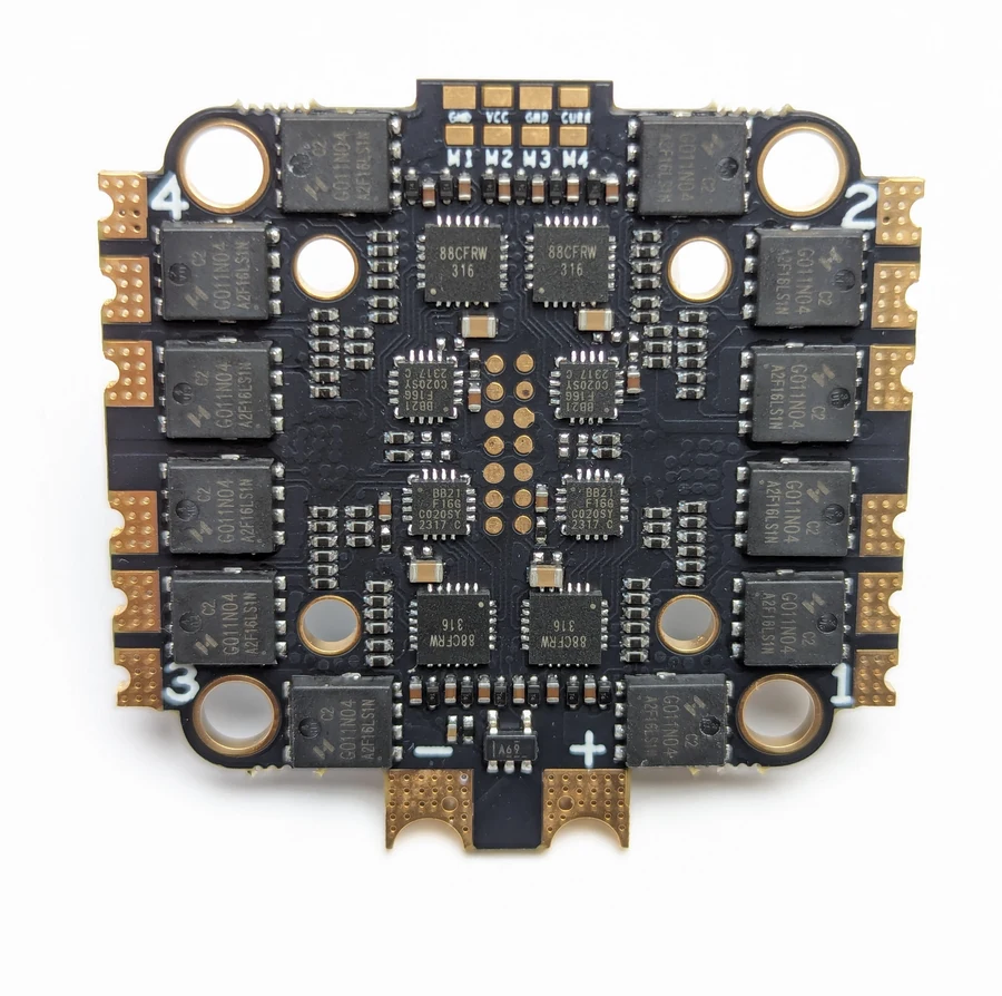
Which one do I need?
| 30A | 33A | 50A | 60A | |
|---|---|---|---|---|
| Battery | 2–4S | 2–6S | 2–6S | 3–6S |
| MOSFET RDS(on) | 3.1 mΩ | 1.2 mΩ | 1.1 mΩ | 0.7 mΩ |
| Suggested airframe | 2–3.5 inch | small 6S builds | 3.5–7 inch | 5–10 inch |
| Board size | 29 × 31 × 5.3 mm | 29 × 31 × 5.3 mm | 44 × 43.5 × 5.2 mm | 44 × 43.5 × 5.2 mm |
| Weight | 5 g | 5 g | 12.5 g | 13.5 g |
| Mounting | 20 × 20 mm (Φ3) | 20 × 20 mm (Φ3) | 30.5 × 30.5 (Φ4) + 20 × 20 (Φ3) | 30.5 × 30.5 mm (Φ4) |
Shared by all four: Bluejay firmware, 48 kHz PWM, DShot300/600 with bidirectional DShot, a 12.75 mV/A current sensor, and an SH1.0-8P connector.
It is the resistance of the MOSFETs that switch the motor current, and lower is better. Resistance turns current into heat, and heat is what kills ESCs — so a lower figure means less waste, a cooler board and more margin under sustained load. It matters more than the headline amp rating when you are choosing between two ESCs that both "fit".
Choosing in practice:
- 30A / 33A — the 20 × 20 mm board for small quads. The 33A is the one to pick: same size and weight, but 6S-capable and with roughly a third of the resistance.
- 50A — the default for most 5-inch builds, and the most flexible to mount because it has both hole patterns. This is the ESC in our F405 V2 stack.
- 60A — the lowest resistance of the family, for 5–10 inch aircraft. Note the 3S minimum.
Where to buy
Ships from Canada with free Canada-wide shipping:
- MicoAir 50A 4-in-1 Bluejay ESC — 2–6S, dual hole spacing
- MicoAir 33A 4-in-1 Bluejay ESC — 2–6S, 20 × 20 mm, 5 g
- F405 V2 + 50A Bluejay stack — flight controller and ESC together
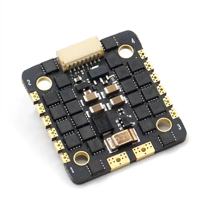
What is in the box
For the 50A: the ESC, three silicone wire sets, a capacitor, an XT60 plug, and four M3 rubber grommets.
The capacitor is not a spare part. See Fit the capacitor below.
Connector pinout
All models use the same SH1.0-8P connector with the same pin order:

| Pin | Function |
|---|---|
| Curr | Current-sensor output to the flight controller — 12.75 mV per amp |
| NC | Not connected |
| M4 – M1 | Motor signal inputs from the flight controller's outputs |
| VBAT | Raw battery voltage out — a 6S pack puts about 22.2 V here |
| GND | Power ground |
It exists to feed the flight controller's own regulator and its voltage sensing. Connecting a receiver, GPS or camera to this pin destroys them.
Installing it

The layout is always the same: the battery feeds the ESC, the ESC feeds the motors, and a single ribbon cable carries signals up to the flight controller. Motor current never goes through the flight controller.
- Battery to the ESC. Solder the battery leads (or an XT60) to the ESC's
+and−pads. Get the polarity right — reversed polarity destroys the board instantly and is not a warranty matter. - Fit the capacitor across the same pads — see below.
- Motors to the ESC. Three thick wires per motor to the pads marked 1, 2, 3 and 4. Motor rotation direction is fixed later in software, so wire order does not matter yet.
- Ribbon to the flight controller using the supplied SH1.0-8P cable.
- Mount the stack on the rubber grommets. They are there to keep motor vibration out of the flight controller's gyro, not just to stop rattling.
Fit the capacitor
The supplied electrolytic capacitor solders across the battery input, positive to positive.
Switching motor currents on and off thousands of times a second puts voltage spikes onto the power rail. The capacitor absorbs them. Without it, those spikes travel into the flight controller and the video system, and the symptoms — noisy gyro data, bars rolling through the FPV feed, random brownouts — get blamed on everything except the missing capacitor.
Remove the propellers before wiring, testing motors, checking direction or changing ESC settings. Motors can start without warning when parameters are written, when the board reboots, or when a test command runs.
Flight controller setup
Set the protocol to DShot300
This is the first thing to do and the most common thing to get wrong.
These ESCs expect a DShot signal. If the flight controller is left on its default output protocol, the ESCs never receive a command they understand — the motors simply do nothing, with no error message, on arming or in motor test. It looks exactly like a dead ESC or a bad solder joint.
DShot300 is the right choice: it is the balance point between bandwidth and reliability, and going faster buys nothing measurable on a normal quad.
Plain DShot sends throttle commands to the ESC as digital numbers — nothing to calibrate, nothing to drift. Bidirectional DShot adds a return path so each ESC reports its actual motor RPM back to the flight controller, which enables RPM-based gyro filtering. These ESCs support it; whether you can use it also depends on the flight controller firmware. ArduPilot and Betaflight do; PX4 and INAV currently do not.
Set the current-sensor scaling
The current sensor outputs 12.75 mV per amp. ArduPilot's BATT_AMP_PERVLT is expressed as amps per volt, so that works out at:
1 V ÷ 0.01275 V/A ≈ 78 A/V
MicoAir's F405 V2 and H743 V2 both ship with BATT_AMP_PERVLT = 40.2, which implies a sensor of about 24.9 mV/A — and that matches neither this ESC nor the AM32 ESCs (12.75 mV/A on the 55A, 10.2 mV/A on the 70A). Whichever ESC you fit, the board default is a placeholder, not a match. Leave it alone with a Bluejay ESC and reported current comes out roughly half the real figure, which makes consumed-mAh and any current-based failsafe wrong in the dangerous direction.
Treat 78 as the starting point rather than the answer. Sensor tolerance varies between boards, so calibrate properly:
- Fly a pack down, or run a known load.
- Compare the mAh the flight controller reported with the mAh your charger puts back in.
- Scale
BATT_AMP_PERVLTby the ratio: if the log says 900 mAh and the charger says 1200 mAh, multiply the parameter by 1200/900. - Repeat once to confirm.
Motor order and direction
With props off, use your ground station's motor test to confirm that motor 1 is where the firmware thinks motor 1 is, and that each spins the right way. Direction is a software setting in Bluejay — reverse it in the ESC configurator rather than by swapping wires.
Full walkthrough: How to Configure Open-Source ESC Parameters.
What Bluejay actually is
Worth understanding, because the ESC firmware landscape is confusing and the names are not descriptive.
| Firmware | Hardware | Notes |
|---|---|---|
| BLHeli_S | 8-bit | The long-standing stock firmware on this class of ESC. No bidirectional DShot. |
| Bluejay | 8-bit | Open-source, runs on the same hardware as BLHeli_S and uses the same configurator. Adds 48 kHz PWM and bidirectional DShot. |
| BLHeli_32 | 32-bit | More capable, closed source, and no longer developed. |
| AM32 | 32-bit | Open-source firmware for 32-bit ESCs — what MicoAir's 55A and 70A ESCs run. |
The practical reason Bluejay matters here is the 48 kHz PWM frequency. Motor switching produces electrical and acoustic noise; pushing the switching frequency up moves that noise away from the band where it disturbs the flight controller's gyro. Cleaner gyro data means the firmware's filters have less to remove, which shows up as steadier flight — particularly in the GPS-assisted modes where noisy attitude estimates do the most damage.
Easily confused points
"The motors don't spin" is usually a protocol setting, not a hardware fault. Set DShot300 before you start desoldering anything.
A 4-in-1 ESC is four ESCs, not one. One of the four can fail on its own. If exactly one motor misbehaves, suspect that channel rather than the whole board.
VBAT is not a 5 V rail. Battery voltage, straight through.
The amp rating is not the whole story. RDS(on) tells you how hot it will run, which is what usually decides whether an ESC survives a demanding build.
The capacitor is a component, not packaging. Builds without it work — until they intermittently don't, in ways that look like every other problem.
Motor numbering is the firmware's, not the frame's. Use the motor test to find out which output the firmware calls motor 1 before you fit props.
The 30A and 33A are not the same ESC. Same board size and weight, but the 33A takes 6S and has roughly a third the resistance.
Troubleshooting
| Symptom | Where to look |
|---|---|
| No motors respond at all | ESC protocol not set to DShot300; ribbon cable not seated; ESC not getting battery power (USB alone does not power motors). |
| One motor does not spin | That channel: motor solder joints, motor itself, or that one ESC. Swap the motor to another output to find out which. |
| Motors spin the wrong way | Reverse the direction in the ESC configurator; don't swap motor wires. |
| Motors stutter or desync | Try DShot300 if you were on 600; check for a missing or failed capacitor; check motor solder joints. |
| Current reading is about half the real value | BATT_AMP_PERVLT left at the board default. See the scaling section above. |
| Noisy gyro, bars in the video | Missing capacitor, or the stack mounted hard to the frame instead of on its grommets. |
| ESC runs very hot | Undersized for the build — compare RDS(on) and the suggested airframe size. |
Related guides
- How to Configure Open-Source ESC Parameters — connecting to the ESC and changing its settings
- MicoAir 4-in-1 AM32 ESC — User Manual — the 32-bit 55A and 70A boards
- F405 V2 Flight Controller — User Manual — the usual partner for the 50A
- H743 V2 Flight Controller — User Manual
- Firmware Flashing Guide
Written and maintained by the Robofusion engineering team.