MicoAir F405 V2 Flight Controller — User Manual
The MicoAir F405 V2 (board name: MicoAir405v2) is a cost-effective 30.5×30.5 flight controller for ArduPilot and INAV builds. Its claim to fame: it was the first F405 board to pair the budget STM32F405 processor with the Bosch BMI088 — an industrial-grade IMU whose temperature stability and vibration robustness are normally found on much more expensive autopilots. If you want a reliable GPS-mission-capable long-range build without paying H7 money, this is the board.
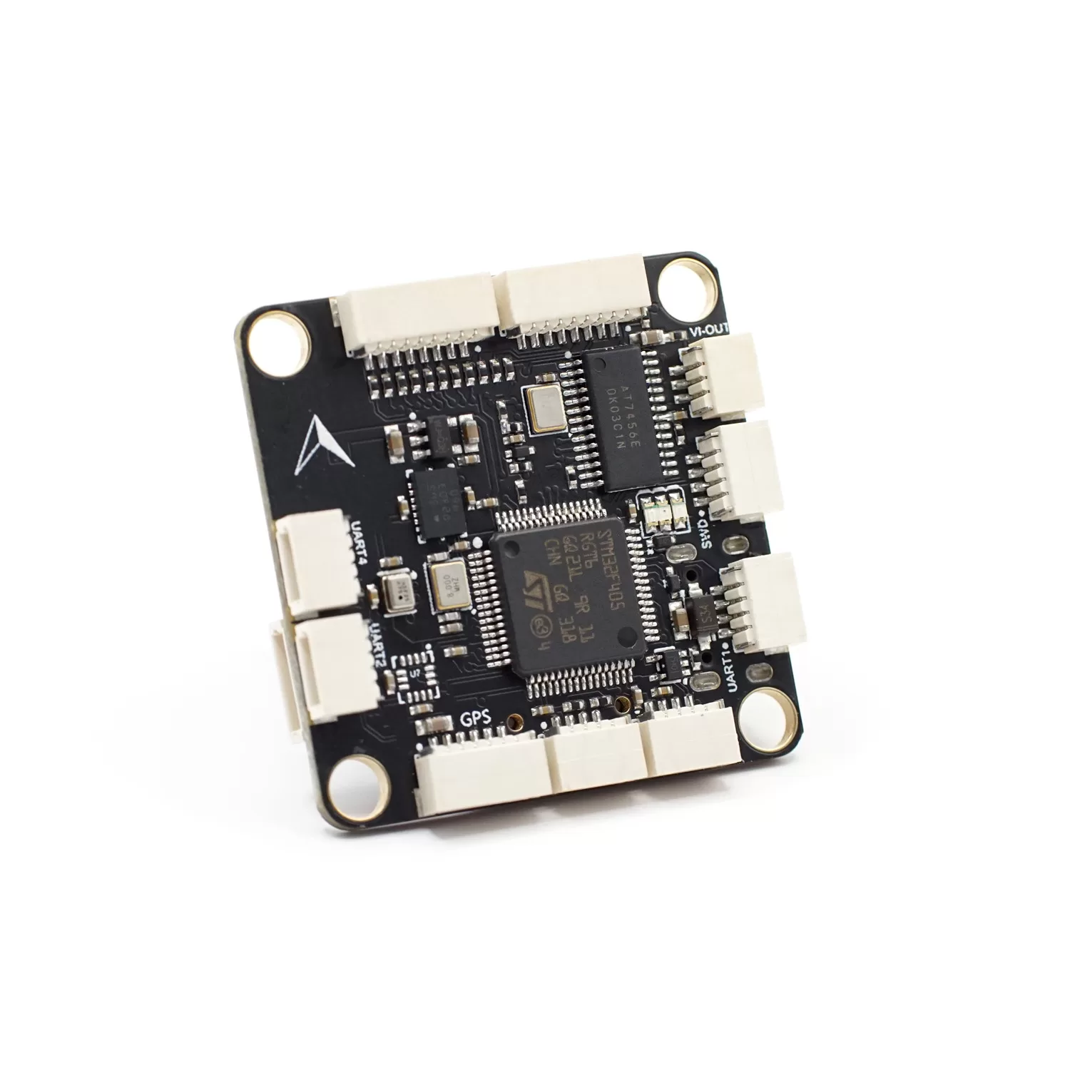
Where to buy
- Robofusion store (ships from Canada — free Canada-wide shipping): MicoAir F405 V2 Flight Controller — FC only, or as a stack with a 50 A Bluejay 4-in-1 ESC
A flight controller's real job is reading its IMU (gyro + accelerometer) cleanly. A fast CPU with a noisy IMU still flies badly; a modest CPU with a clean IMU flies beautifully. The BMI088 on this board was designed by Bosch for drones and robotics — it shrugs off motor vibration that makes hobby-grade IMUs drift. That is why an F405 board with a BMI088 can out-fly pricier boards on paper specs. The trade-off of the older F405 processor: fewer UARTs and less headroom for heavy logging or Lua scripting — see the comparison below.
F405 V2, H743 V2, or NxtPX4 V2 — which one?
| F405 V2 | H743 V2 | NxtPX4 V2 | |
|---|---|---|---|
| Processor | STM32F405, 168 MHz | STM32H743, 480 MHz | STM32H743, 480 MHz |
| IMU | BMI088 | BMI088 + BMI270 (dual) | BMI088 × 2 (dual) |
| Firmware | ArduPilot / INAV | ArduPilot / PX4 / INAV / Betaflight | PX4 (native) / ArduPilot |
| UARTs / PWM | 6 / 10 | 8 / 11 | 7 / 8 |
| Mounting | 30.5 × 30.5 mm | 30.5 × 30.5 mm | 20 × 20 mm |
| Best for | Budget long-range ArduPilot/INAV | Do-it-all flagship | Small PX4 research drones |
Specifications
| Item | Specification |
|---|---|
| MCU | STM32F405RGT6, 168 MHz, 1 MB flash |
| IMU | BMI088 (Bosch, 6-axis) |
| Barometer | SPL06 |
| OSD chip | AT7456E (analog OSD) |
| Logging | MicroSD card slot |
| Interfaces | 6× UART, 10× PWM, 1× I2C, 1× SWD, 2× ADC (voltage / current) |
| USB | Type-C |
| HD VTX connector | SH1.0-6P for DJI O3 Air Unit |
| BEC | 5 V 3 A (receiver, GPS, optical flow…) + 9 V 3 A (VTX, camera) |
| Battery input | 2–6S LiPo, on-board voltage sensing |
| Compass | None built-in — connect external via I2C (SDA/SCL) |
| Mounting | 30.5 × 30.5 mm, Φ4 mm holes |
| Dimensions / weight | 36 × 36 × 8 mm / 9 g |
Pinout
Top and bottom pad layout:
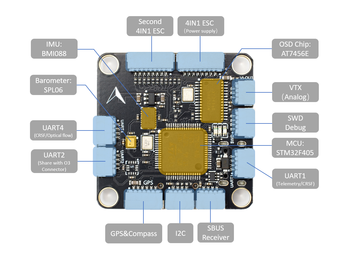
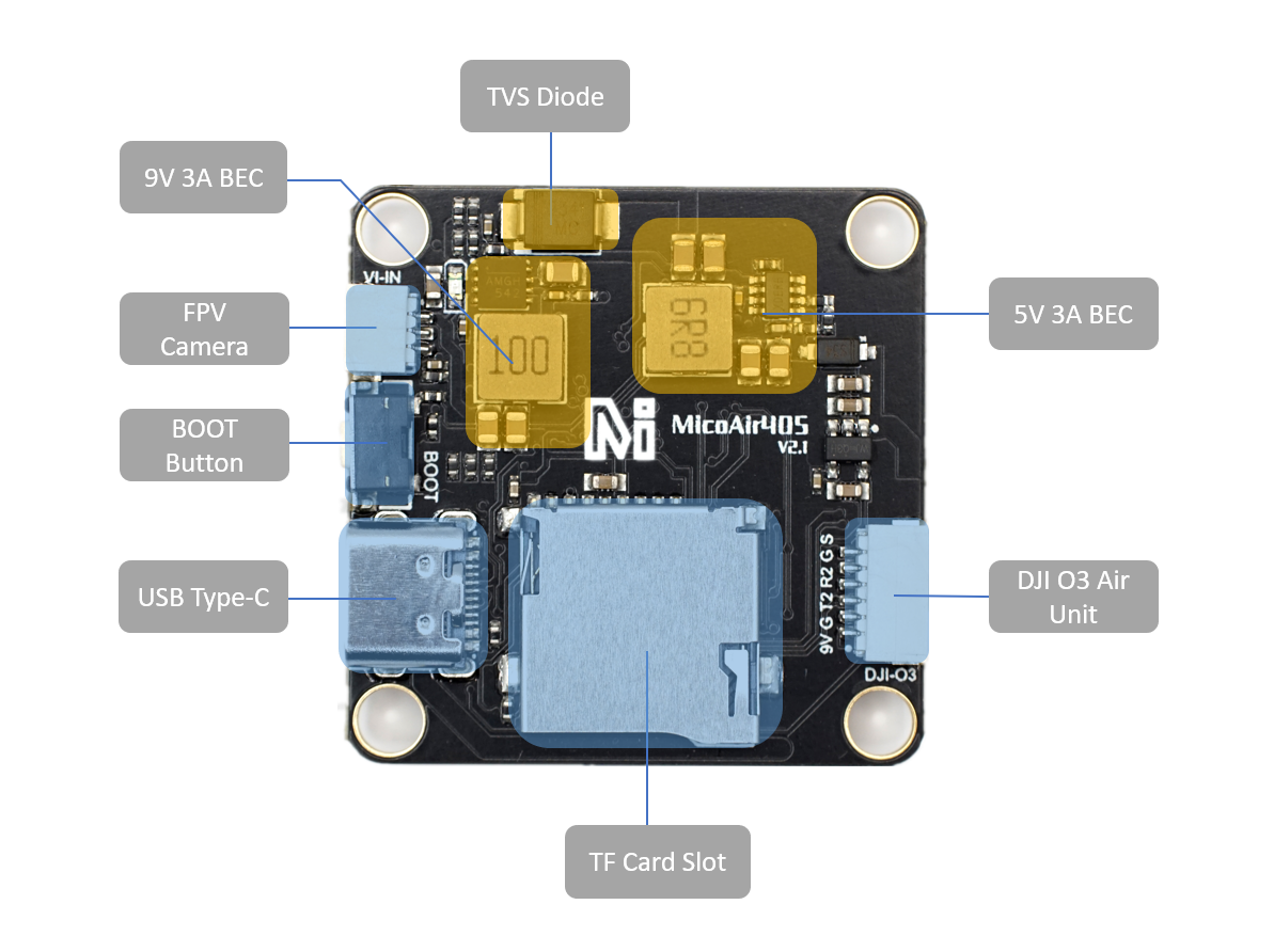
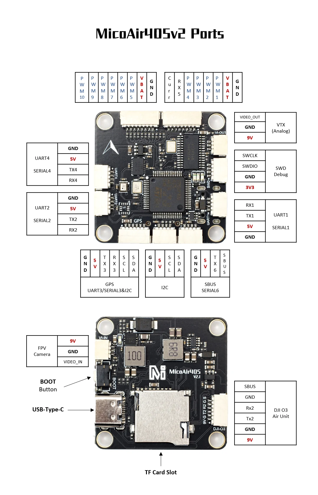
Connector pin list
Pins are listed in the order printed on MicoAir's port diagram. Before plugging anything in, match the first and last pin against the silkscreen next to the connector — the diagram shows which end is which, a text table cannot.
| Connector | Pins | Port (ArduPilot) | Notes |
|---|---|---|---|
| 4-in-1 ESC (power supply, 8-pin) | Curr · RX5 · PWM4 · PWM3 · PWM2 · PWM1 · VBAT · GND | RX5 = SERIAL5 | ESC telemetry on RX5; current sensor on Curr |
| Second 4-in-1 ESC (8-pin) | PWM10 · PWM9 · PWM8 · PWM7 · PWM6 · PWM5 · VBAT · GND | — | extra motors or servos |
| GPS & compass | GND · 5V · TX3 · RX3 · SCL · SDA | UART3 = SERIAL3, I2C | |
| I2C | GND · 5V · SCL · SDA | I2C | external compass or sensors |
| SBUS receiver | GND · 5V · TX6 · SBUS | SERIAL6 | RX6 inverted from the SBUS pin |
| UART1 | RX1 · TX1 · 5V · GND | SERIAL1 | spare — good for CRSF/ELRS |
| UART2 | GND · 5V · TX2 · RX2 | SERIAL2 | shared with the DJI O3 connector |
| UART4 | GND · 5V · TX4 · RX4 | SERIAL4 | spare |
| DJI O3 Air Unit (6-pin) | 9V · GND · TX2 · RX2 · GND · SBUS | SERIAL2 | 9 V on this connector; silkscreen 9V G T2 R2 G S |
| Analog VTX | VIDEO_OUT · GND · 9V | — | 9 V supply |
| FPV camera | 9V · GND · VIDEO_IN | — | 9 V supply — not for 5 V cameras |
| SWD debug | SWCLK · SWDIO · GND · 3V3 | — | recovery and debugging only |
Also on the board: USB-C, the BOOT button, and a microSD slot. BECs: 9 V 3 A and 5 V 3 A.
UART mapping
| Port | ArduPilot | Default function |
|---|---|---|
| USB | SERIAL0 | GCS connection |
| UART1 | SERIAL1 | Spare (DMA) — good for CRSF/ELRS |
| UART2 | SERIAL2 | DJI HD VTX (DisplayPort, DMA) |
| UART3 | SERIAL3 | GPS |
| UART4 | SERIAL4 | Spare (DMA) |
| UART5 | SERIAL5 | ESC telemetry — RX only |
| UART6 | SERIAL6 | SBUS input (RX6 inverted from SBUS pin; TX6 has no DMA) |
RC input
- SBUS receivers — use the dedicated SBUS pin (internally inverted into RX6); works out of the box
- CRSF / ELRS and other bidirectional protocols — use a full UART such as UART1 or UART4: wire RX/TX, set that port's
SERIALn_PROTOCOL = 23, and changeSERIAL6_PROTOCOLto anything other than 23 - PPM is not supported
Typical setup: ELRS receiver TX → R1 pad, receiver RX → T1 pad, then SERIAL1_PROTOCOL = 23, SERIAL6_PROTOCOL = 0. Done — full telemetry included.
OSD and HD VTX
- Analog OSD — onboard AT7456E (
OSD_TYPE = 1), pairs with analog VTX modules like the VT5804 / VT5805 - DJI O3 — SH1.0-6P connector with DisplayPort OSD on UART2
Pin 1 of the SH1.0-6P connector carries the 9 V BEC rail for the video system. Never wire a 5 V peripheral to it.
PWM outputs and DShot
10 PWM outputs; channels 1–8 support DShot, channels 1–4 additionally support bi-directional DShot (RPM telemetry for gyro filtering). Outputs are grouped — every output in a group must run the same protocol:
| Group | Outputs |
|---|---|
| 1 | 1, 2, 5, 6 |
| 2 | 3, 4 |
| 3 | 7, 8 |
| 4 | 9, 10 |
Note that the grouping does not follow the output numbering: outputs 1, 2, 5 and 6 share one timer, while 3 and 4 share another. A four-motor quad therefore spans two groups, and changing the protocol on outputs 1–4 touches 5 and 6 as well.
Remove the propellers before testing motors, reordering them or calibrating ESCs. Motors can start unexpectedly when parameters are written, when the board reboots, or when a test command runs.
Outputs 3 and 4 sit on TIM2 while 1, 2, 5 and 6 sit on TIM3. If MOTOR3 and MOTOR4 are dead in INAV, set both Timer2 and Timer3 to the MOTORS function in the configurator's timer mapping — INAV does not always assign them automatically.
Battery monitoring
Voltage sensing is built in (up to 6S); current sensing comes from the 4-in-1 ESC via the ESC connector. Default ArduPilot parameters:
| Parameter | Value |
|---|---|
BATT_VOLT_PIN | 10 |
BATT_CURR_PIN | 11 |
BATT_VOLT_MULT | 21.2 |
BATT_AMP_PERVLT | 40.2 |
The current scale (BATT_AMP_PERVLT) depends on the current-sensing circuit in whichever ESC you actually fit, so the default is a starting point rather than a calibration — verify against a charger's mAh count after a few flights and adjust.
Compass
No compass on the board. For GPS missions add an external compass — the usual route is a GPS+compass combo module (e.g. an M10 GPS with QMC5883L) wired to the SDA/SCL pads. Mount it on a mast away from power wiring.
Firmware
| Firmware | Support | Target / notes |
|---|---|---|
| ArduPilot | Official since 4.5.0 | Target MicoAir405v2 — builds on firmware.ardupilot.org, or the custom firmware builder |
| INAV | Official since 8.0 | Target MICOAIR405V2; older builds on micoair GitHub |
Betaflight and PX4 are not supported on this board — if you need them, use the H743 V2.
MicoAir's board list has several similarly named entries — the H743 boards, the Lite and the AIO variants. Flashing a near-miss target produces a board that boots normally but has the wrong pin map, so motors, GPS and battery sensing all land on the wrong pins. Read the target name character by character.
First-time flashing (DFU)
- Disconnect USB and battery.
- Hold the BOOT button, keep holding it, and plug in USB-C.
- Release once the computer enumerates the DFU device.
- Flash the
arduXXXX_with_bl.hexfile with a DFU tool (or Mission Planner → Load custom firmware, or MicoConfigurator). - Afterwards, update over USB with
.apjfiles from any ground station.
A board in DFU mode shows up as a DFU device rather than a COM port, and its LEDs stay dark. Both are normal.
Easily confused points
The SBUS pin is not a UART. It runs through a hardware inverter and is receive-only. SBUS works there; CRSF, ELRS and FPort do not, and no amount of parameter changing will fix that — they need a real full-duplex UART such as UART1 or UART4.
.hex vs .apj. The _with_bl.hex file contains the bootloader and the firmware, and is what you flash over DFU on a blank or bricked board. An .apj file is firmware only, flashed by a ground station through the bootloader already on the board.
Pin 1 of the HD VTX connector is 9 V on this board — not 5 V, and not the 12 V of the H743 V2. Wiring a 5 V peripheral there destroys it.
Timer groups don't follow output numbers. Outputs 1, 2, 5, 6 share a timer; 3 and 4 share another. See the group table above before changing a protocol.
DShot and bi-directional DShot cover different outputs here. Outputs 1–8 do DShot; only 1–4 do bi-directional DShot. A hexacopter cannot get RPM telemetry from all six motors on this board.
There is no compass on the board. Unlike the H743 V2, this one has nothing to fall back on — GPS missions need an external compass on the I2C pads.
FAQ
Is an F405 still worth buying in the H7 era?
For ArduPilot/INAV cruising builds — yes. The F405 runs standard GPS missions, OSD, and DShot without breaking a sweat. You give up spare UARTs, heavy logging headroom, and Lua scripting. If the price difference doesn't matter to you, buy the H743 V2; if it does, this board flies just as straight.
Can it run DJI O3 and analog video at the same time?
The board has both paths (AT7456E analog OSD + DJI connector on UART2), so yes — a common setup is O3 for the pilot feed and an analog VTX as a cheap long-range backup.
The motors don't respond to arming or motor test with the Bluejay ESC on ArduPilot
Set the ESC protocol to DShot300. The 50 A Bluejay 4-in-1 that ships in the stack bundle expects a DShot protocol, and with ArduPilot's default output protocol it simply never sees a valid command — the motors stay silent, with no error to point at. This is the first thing to check on a freshly assembled stack.
Why does my SBUS receiver work but my ELRS receiver doesn't on the SBUS pin?
The SBUS pin runs through a hardware inverter and is receive-only — bidirectional protocols like CRSF/ELRS need a real UART pair. Use UART1 or UART4 as described in RC input.
Related guides
- F405 V2 — Beginner ArduPilot Setup Guide — frame, motors, receiver, calibration and first arming
- MicoAir F405 Mini — User Manual — the 20 × 20 mm sibling
- H743 V2 Flight Controller — User Manual
- NxtPX4 V2 Flight Controller — User Manual
- ArduPilot — Telemetry Setup Guide
- VT5804 5.8 GHz 2.5W Video Transmitter — User Manual
Written and maintained by the Robofusion engineering team.