SERVOMY SDS1901 Micro Servo — User Manual
A servo turns a control signal into a precise angle and holds it there — the part that moves a control surface, steers a wheel or aims a camera. The SDS1901 is a micro servo in the familiar 9 g form factor, built considerably more solidly than the plastic-geared hobby servos that shape usually implies: full metal case, metal gears, a coreless motor, digital control, and support for high-voltage operation up to 8.4 V.
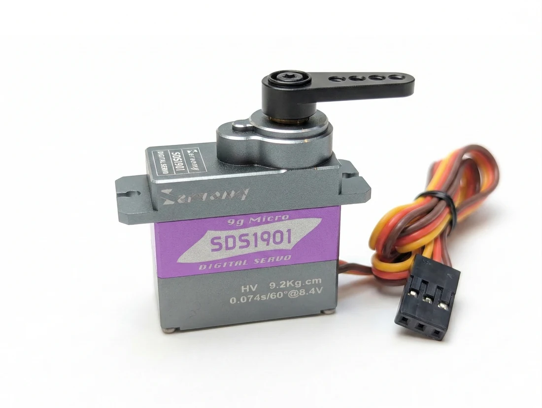
The SDS1901 fits the mounting space of a 9 g micro servo — the same cutout an SG90 or MG90S drops into — but it actually weighs 19 g, because the metal case and metal gears are heavier than the plastic they replace. On a small airframe those extra 10 grams are worth checking before you commit.
Where to buy
- SERVOMY SDS1901 Micro Servo — ships from Canada with free Canada-wide shipping
Specifications
| Item | Specification |
|---|---|
| Model | SDS1901 |
| Type | Digital micro servo |
| Motor | Coreless |
| Operating voltage | 5.0 – 8.4 V DC |
| Rotation | 180° |
| Dimensions | 24 × 12 × 22 mm |
| Weight | 19 g |
| Case | Full metal |
| Gears | Metal |
| Bearings | 1 ball bearing |
| Reduction ratio | 390:1 |
| Output spline | 21T, 4.9 mm |
| Angle sensor | Potentiometer |
| Lead length | 310 ± 10 mm, 26 AWG |
| Control | PWM |
| Recommended pulse | 1000 – 2000 µs |
| Accepted pulse range | 500 – 2500 µs |
| Neutral | 1520 µs |
| Dead band | 2 µs |
| Refresh rate | up to 333 Hz |
| Rotation direction | forward / reverse |
| Operating temperature | −10 °C to 50 °C |
| Waterproof | No |
Voltage decides torque and speed
This is the specification that matters most, and it is a straight trade rather than a single number:
| Supply | Speed (no load) | Stall torque |
|---|---|---|
| 5.0 V | 0.16 s / 60° | 6.8 kgf·cm |
| 6.0 V | 0.13 s / 60° | 7.5 kgf·cm |
| 7.4 V | 0.09 s / 60° | 8.0 kgf·cm |
| 8.4 V | 0.07 s / 60° | 9.2 kgf·cm |
From 5 V to 8.4 V you gain about a third more torque and more than twice the speed.
Which to use:
- 5 V — the flight controller's BEC rail. Simplest, safest, and enough for light control surfaces or a small pan-tilt.
- 6 V — a common receiver-pack voltage, a useful middle ground.
- 7.4 V / 8.4 V — a 2S LiPo, for the full figures. Make sure whatever supplies it can deliver the stall current, which is far higher than the running current; a small BEC that copes at idle can brown out when the servo hits a mechanical limit.
5.0–8.4 V is this servo's range. Feeding 8.4 V to a basic 5 V micro servo sitting beside it on the same rail will destroy that one. If you mix servo types on one aircraft, run them on separate rails or on the lowest common voltage.
Wiring
| Wire | Function |
|---|---|
| Yellow | signal (PWM) |
| Red | positive |
| Brown | negative / ground |
Most servo leads use black for ground, and a brown wire reads as "the odd one out" to anyone expecting that. Brown is ground here. Getting the connector round the wrong way applies reverse polarity to the servo.
Connect the signal wire to a flight controller output or a receiver channel, and power and ground to a supply within 5.0–8.4 V that shares a ground with the signal source.
The control signal

A servo is commanded by the width of a pulse, repeated continuously. Not the voltage, not the frequency — the width.
- 1000 µs → one end of travel
- 1520 µs → neutral (centre)
- 2000 µs → the other end
Two details specific to this servo:
Neutral is 1520 µs, not 1500. Most sources quote 1500 µs as the universal centre. If the output sits very slightly off centre with a 1500 µs command, that is why — trim it in the flight controller rather than mechanically.
It accepts up to 333 Hz. A basic analog servo expects around 50 Hz. A digital servo that will take 333 Hz updates its position far more often, which is what makes it hold position more firmly and respond more crisply. If your flight controller lets you raise the servo update rate, this one can use it.
The accepted range of 500–2500 µs is wider than the recommended 1000–2000 µs. It will follow commands out there, but past the mechanical limit it will push against its own end stop, drawing current and generating heat for no movement. Set your endpoints inside the mechanical range.
Fitting the horn
The output spline is 21T, 4.9 mm — the common micro-servo spline, so third-party horns in that size fit.
An aluminium horn is included, along with a set of plastic horns and hardware.
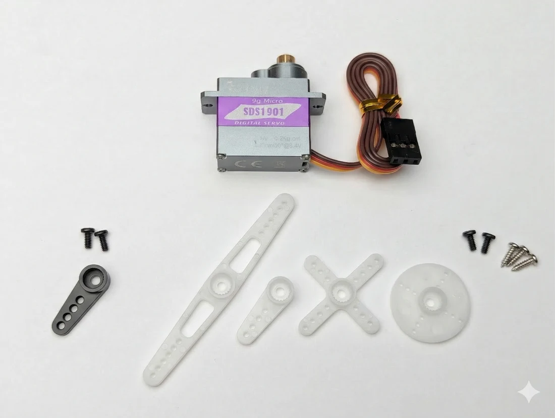
Centre the servo before fitting the horn. Send a neutral (1520 µs) command, let it settle, then fit the horn at the angle you want as its centre position. Fitting a horn to an un-centred servo costs you travel at one end and gives you more than you can use at the other.
What the metal build buys you
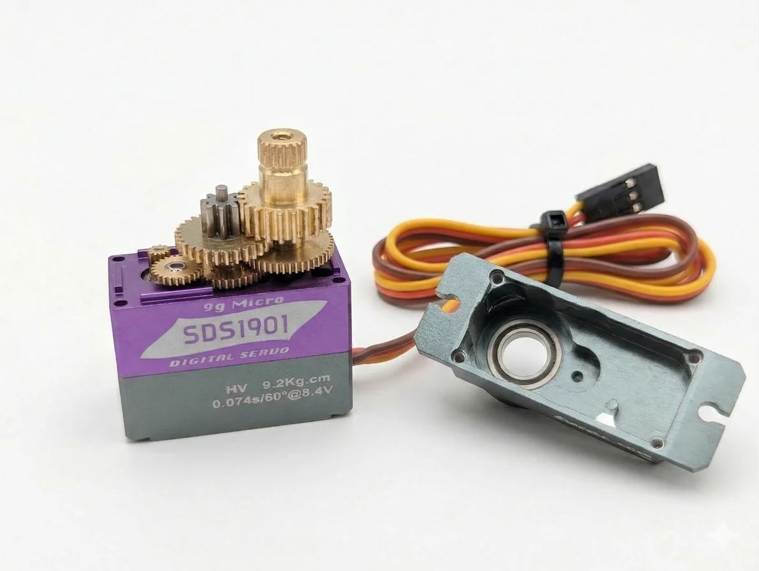
Three things distinguish this from a basic micro servo, and each has a practical consequence:
- Metal gears — plastic gear teeth strip under shock loads, which on a model usually means a heavy landing or a control surface catching something. Metal gears survive that; it is the most common failure mode they remove.
- Full metal case — better heat dissipation as well as mechanical protection. A servo working hard gets warm, and metal sheds that heat.
- Coreless motor — lighter rotor, so it accelerates and stops faster. That is where the quick response and crisp centring come from, rather than from raw torque.
The costs are the extra 10 grams and a higher price than a plastic 9 g servo.
Typical uses
- RC car steering
- Fixed-wing control surfaces
- Micro helicopter linkages
- Robotic joints and small actuators
- Pan-tilt mechanisms and camera mounts
Easily confused points
"9 g" is the form factor, not the weight. This one is 19 g.
Neutral is 1520 µs, not 1500 µs.
Ground is the brown wire, where most leads use black.
Recommended range and accepted range are different numbers. 1000–2000 µs for normal use; 500–2500 µs is what it tolerates.
High voltage is optional, not required. It runs perfectly well at 5 V, with less torque and speed.
Stall current is the number that sizes your supply, not running current.
Not waterproof. Metal case, no sealing.
Troubleshooting
| Symptom | Where to look |
|---|---|
| Does not move at all | Signal on the yellow wire? Supply within 5.0–8.4 V? Ground shared with the signal source? |
| Jitters or buzzes at rest | Usually a noisy supply or a signal source with poor timing. Try a separate supply rail. |
| Gets hot without moving | It is stalled against a mechanical limit — reduce the endpoint travel. |
| Slightly off centre at 1500 µs | Neutral on this servo is 1520 µs. Trim it in the flight controller. |
| Browns out the flight controller | Stall current on a shared 5 V rail. Give the servo its own supply. |
| Slow or weak | Running at 5 V. Check the voltage table for what higher voltage buys. |
| Horn hits its limit before full travel | The horn was fitted with the servo off-centre. Re-centre and refit. |
Written and maintained by the Robofusion engineering team.