MicoAir GPS Module User Manual
A GPS module is what lets an autopilot know where it is, and therefore what makes position hold, return-to-home and waypoint missions possible at all. The modules on this page are the ordinary, everyday kind: a GNSS receiver and a magnetic compass in one small puck, on one cable, for a price that makes fitting one to every build reasonable.
Four models share the same connector, the same wiring and the same setup procedure, differing in receiver chip, size and update rate:
| MG-A01 | M10G-5883 | MG-902 | MG-903 | |
|---|---|---|---|---|
| GNSS chip | u-blox M10050 | u-blox M10050 | u-blox M9140 | u-blox M9140 |
| Compass | QMC5883L | QMC5883L | QMC5883L | IST8310 |
| Concurrent constellations | 3 | 3 | 4 | 4 |
| Navigation update rate | 10 Hz | 5 Hz | 25 Hz | 25 Hz |
| Max satellites | 32 | 32 | 32 | 32 |
| Tracking sensitivity | −167 dBm | −167 dBm | −167 dBm | −167 dBm |
| Size | 25 × 25 × 8 mm | 20 × 20 × 8 mm | 25 × 25 × 8 mm | 20 × 20 × 8 mm |
| Weight | 12 g | 7 g | 12 g | 7 g |
All four have on-board flash, speak NMEA and UBX, and use an SH1.0-6P connector.
There are several independent satellite navigation systems in orbit — GPS (US), GLONASS (Russia), BeiDou (China), Galileo (EU) and QZSS (Japan). A receiver that can track more of them at once sees more satellites, which matters most where the sky is partly blocked: near buildings, under trees, in a valley. Three concurrent is fine for open-field flying; four helps in cluttered places.
Satellite signals received
- MG-A01 / M10G-5883 — GPS L1 C/A; GLONASS L1OF; BeiDou B1I/B1C; Galileo E1B/C; QZSS L1 C/A/S; SBAS L1 C/A
- MG-902 / MG-903 — GPS L1 C/A; GLONASS L1OF; BeiDou B1I; Galileo E1B/C; QZSS L1 C/A/S; SBAS L1 C/A
Which one should you buy?
- M10G-5883 — the default choice. Small, light, 20 × 20 mm, and the M10 generation's low power draw. A 5 Hz position update is more than enough for a multirotor flying waypoints.
- MG-903 — the same 20 × 20 mm footprint with the M9140's four-constellation reception and a 25 Hz update rate, plus the IST8310 compass, which is the magnetometer most ArduPilot builders prefer. The upgrade pick at this size, and a drop-in replacement for older M9N-5883 modules.
- MG-A01 — the 25 × 25 mm version of the M10G-5883, with a bigger antenna patch and a 10 Hz update rate. Larger antenna, slightly better reception, more space needed on the airframe.
- MG-902 — the 25 × 25 mm M9140 module with a QMC5883L compass.
Where to buy
Ships from Canada with free Canada-wide shipping:
- M10G-5883 — M10 GPS + QMC5883L compass — 20 × 20 mm, 7 g
- MG-903 — M9 GNSS + IST8310 compass — 20 × 20 mm, 7 g, replaces the M9N-5883
- MG-A01 — 25 mm M10 GNSS + compass — 25 × 25 mm, 12 g
Need centimetre accuracy instead of metre accuracy? See the MA-RTK series and What Is RTK?.
The modules
M10G-5883
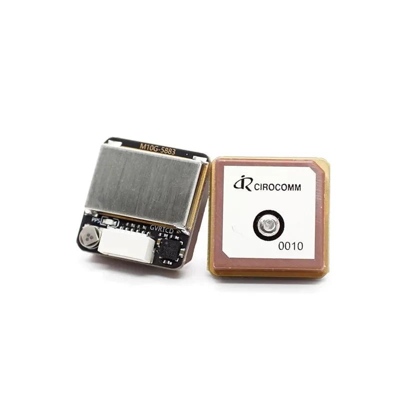
| Item | Specification |
|---|---|
| GNSS chip | u-blox M10050 |
| Compass chip | QMC5883L |
| Constellations | GPS L1 C/A; GLONASS L1OF; BeiDou B1I/B1C; Galileo E1B/C; QZSS L1 C/A/S; SBAS L1 C/A |
| Concurrent constellations | 3 |
| Navigation update rate | 5 Hz |
| Max satellites | 32 |
| Tracking sensitivity | −167 dBm |
| Flash | on board |
| Protocols | NMEA / UBX |
| Size / weight | 20 × 20 × 8 mm / 7 g |
| Connector | SH1.0-6P |
MG-903
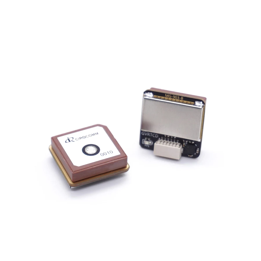
| Item | Specification |
|---|---|
| GNSS chip | u-blox M9140 |
| Compass chip | IST8310 |
| Constellations | GPS L1 C/A; GLONASS L1OF; BeiDou B1I; Galileo E1B/C; QZSS L1 C/A/S; SBAS L1 C/A |
| Concurrent constellations | 4 |
| Navigation update rate | 25 Hz |
| Max satellites | 32 |
| Tracking sensitivity | −167 dBm |
| Flash | on board |
| Protocols | NMEA / UBX |
| Size / weight | 20 × 20 × 8 mm / 7 g |
| Connector | SH1.0-6P |
MG-A01
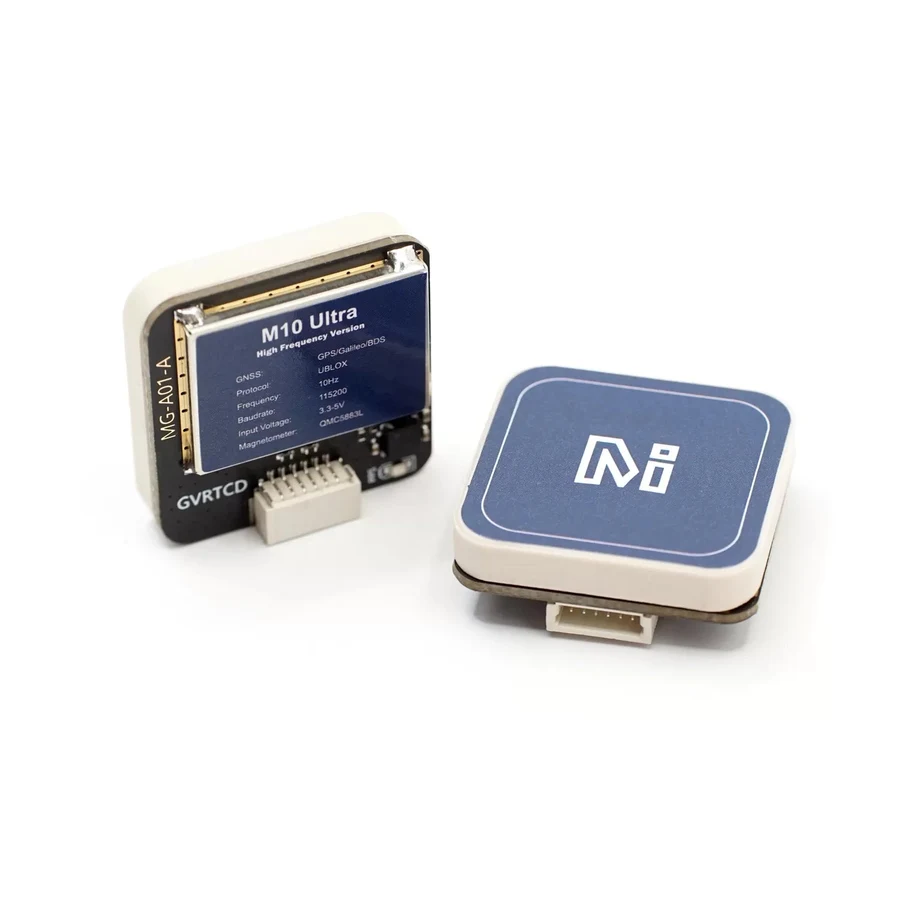
| Item | Specification |
|---|---|
| GNSS chip | u-blox M10050 |
| Compass chip | QMC5883L |
| Constellations | GPS L1 C/A; GLONASS L1OF; BeiDou B1I/B1C; Galileo E1B/C; QZSS L1 C/A/S; SBAS L1 C/A |
| Concurrent constellations | 3 |
| Navigation update rate | 10 Hz |
| Max satellites | 32 |
| Tracking sensitivity | −167 dBm |
| Flash | on board |
| Protocols | NMEA / UBX |
| Size / weight | 25 × 25 × 8 mm / 12 g |
| Connector | SH1.0-6P |
MG-902
| Item | Specification |
|---|---|
| GNSS chip | u-blox M9140 |
| Compass chip | QMC5883L |
| Constellations | GPS L1 C/A; GLONASS L1OF; BeiDou B1I; Galileo E1B/C; QZSS L1 C/A/S; SBAS L1 C/A |
| Concurrent constellations | 4 |
| Navigation update rate | 25 Hz |
| Max satellites | 32 |
| Tracking sensitivity | −167 dBm |
| Flash | on board |
| Protocols | NMEA / UBX |
| Size / weight | 25 × 25 × 8 mm / 12 g |
| Connector | SH1.0-6P |
Baud rates and protocol
| Setting | Value |
|---|---|
| Module factory baud rate (all four) | 115200 |
| Module factory protocol | UBX, NAV-PVT messages |
| Chip default baud — MG-A01 / M10G-5883 | 38400 |
| Chip default baud — MG-902 / MG-903 | 9600 |
The two rows worth understanding: the chip default and the module default are different numbers. MicoAir configures each module to 115200 before it ships, so 115200 is what you will actually see. The chip default only reappears if the module's saved configuration is wiped — and it can be set back with u-blox’s u-center tool.
In normal use you do not need to touch any of this. ArduPilot and PX4 detect a u-blox receiver and configure the port themselves.
Wiring
All four modules use the same SH1.0-6P connector with the same pin order:

| Module pin | Connect to | Carries |
|---|---|---|
| GND | flight controller GND | power ground |
| 5V | flight controller 5 V | power |
| Rx | flight controller UART Tx | GPS data |
| Tx | flight controller UART Rx | GPS data |
| SCL | flight controller SCL | compass (I2C) |
| SDA | flight controller SDA | compass (I2C) |
Two things to hold on to:
Rx and Tx cross. "Rx" means this device receives, so it has to meet the other device's transmit line. Using the supplied cable into a flight controller's dedicated GPS port, this is already done for you.
There are two separate sensors on this cable. The GNSS receiver talks over the UART (Rx/Tx); the compass talks over I2C (SCL/SDA). They are independent — which is exactly why "GPS works, compass missing" is such a common and such a solvable fault.
Compass orientation
The compass inside the module is soldered at some fixed angle to the module's own outline, and the flight controller has no way to know what that angle is. You tell it with an orientation parameter — and the value depends on which module you have, because the four do not all mount their magnetometer the same way round.
These values assume the normal mounting: connector pointing towards the tail, printed label facing up.

Mounting the module at some other angle? The External Compass Orientation guide covers all four rotations and the arithmetic behind them.
| Firmware | MG-A01 | M10G-5883 | MG-902 | MG-903 |
|---|---|---|---|---|
| ArduPilot | YAW90 | YAW270 | YAW90 | YAW270 |
| PX4 | ROTATION_PITCH_180 | ROTATION_ROLL_180 | ROTATION_PITCH_180 | ROTATION_ROLL_180_YAW_90 |
| INAV | CW 0° flip | CW 180° flip | CW 0° flip | CW 270° flip |
| Betaflight | CW 0° flip | CW 180° flip | CW 0° flip | CW 270° flip |
If you rotate the module on the airframe — connector to the front, or sideways — the orientation parameter has to change to match. Set it for how the module actually sits, then confirm with a compass calibration and a check that the heading on the map turns the same way the aircraft does.
After setting the orientation, run the normal compass calibration in your ground station. A compass that has never been calibrated on the airframe it is bolted to will be wrong no matter how correct the orientation parameter is.
Mounting
The compass is the reason GPS modules go on masts. A magnetometer measures the Earth's magnetic field, which is weak — and the current flowing through your battery leads and ESCs produces a field that is not weak at all, right next to it.
- Mount the module as far from power wiring, ESCs and motors as practical, usually on a short mast above the frame.
- Keep the module's label facing up and its antenna patch with a clear view of the sky — no carbon plate, canopy or battery above it.
- Keep it away from the video transmitter and its antenna.
- Fix it rigidly. A module that can rotate under vibration produces a heading that drifts with it.
- Calibrate the compass after the aircraft is fully assembled, with the battery in its flying position.
Easily confused points
GPS and compass are two different sensors sharing one plug. "No GPS" and "no compass" are different faults with different causes — the UART pair for one, the I2C pair for the other.
The orientation parameter is not the same as the flight controller's orientation. AHRS_ORIENTATION (ArduPilot) describes how the flight controller is mounted. The compass parameter here describes how the compass is mounted. Setting one when you meant the other gives a heading that is wrong in a confusing way.
The chip's default baud rate is not the module's baud rate. The module ships at 115200 regardless of what the chip's datasheet default is.
Satellite count is not fix quality. A module reporting 20 satellites can still be giving a poor position if HDOP is high or the signals are reflections off a nearby building. Watch HDOP and the reported accuracy figures, not just the satellite count.
A compass that has not been calibrated on the airframe is not a working compass, even with the correct orientation set. Both steps are required.
MG-903 is not "MG-902 plus one". They share a GNSS chip, but the 903 is the 20 × 20 mm board with an IST8310 compass while the 902 is the 25 × 25 mm board with a QMC5883L — and their orientation parameters differ accordingly.
Troubleshooting
| Symptom | What to check |
|---|---|
| No GPS detected at all | Rx/Tx crossed? Flight controller port set to GPS? Module powered — is the 5 V pin live? |
| GPS detected, no satellites | Take it outdoors with a clear sky view. A first fix after long storage can take several minutes. Check nothing is above the antenna patch. |
| GPS fine, compass missing | The I2C pair: SCL and SDA connected, not swapped, and reaching the flight controller's I2C pins. |
| Heading points the wrong way | Wrong orientation value for your specific module — check the table above, remembering the four are not the same. |
| Heading wanders during throttle changes | Magnetic interference from power wiring. Move the module further from the battery leads and ESCs, then recalibrate. |
| Satellite count good, position unstable | Look at HDOP and accuracy rather than satellite count; multipath near buildings and RF noise from a video transmitter both cause this. |
Related guides
- External Compass Orientation in ArduPilot / PX4 / INAV / Betaflight — the full orientation reference, including rotated mounts
- MG-F10-C — Dual-Band GNSS Module — the L1+L5 sub-metre step up
- MA-RTK Series — User Manual — centimetre-level RTK
Written and maintained by the Robofusion engineering team.