MicoAir WiFi Link — Dual-Band WiFi 6 Telemetry Module User Manual
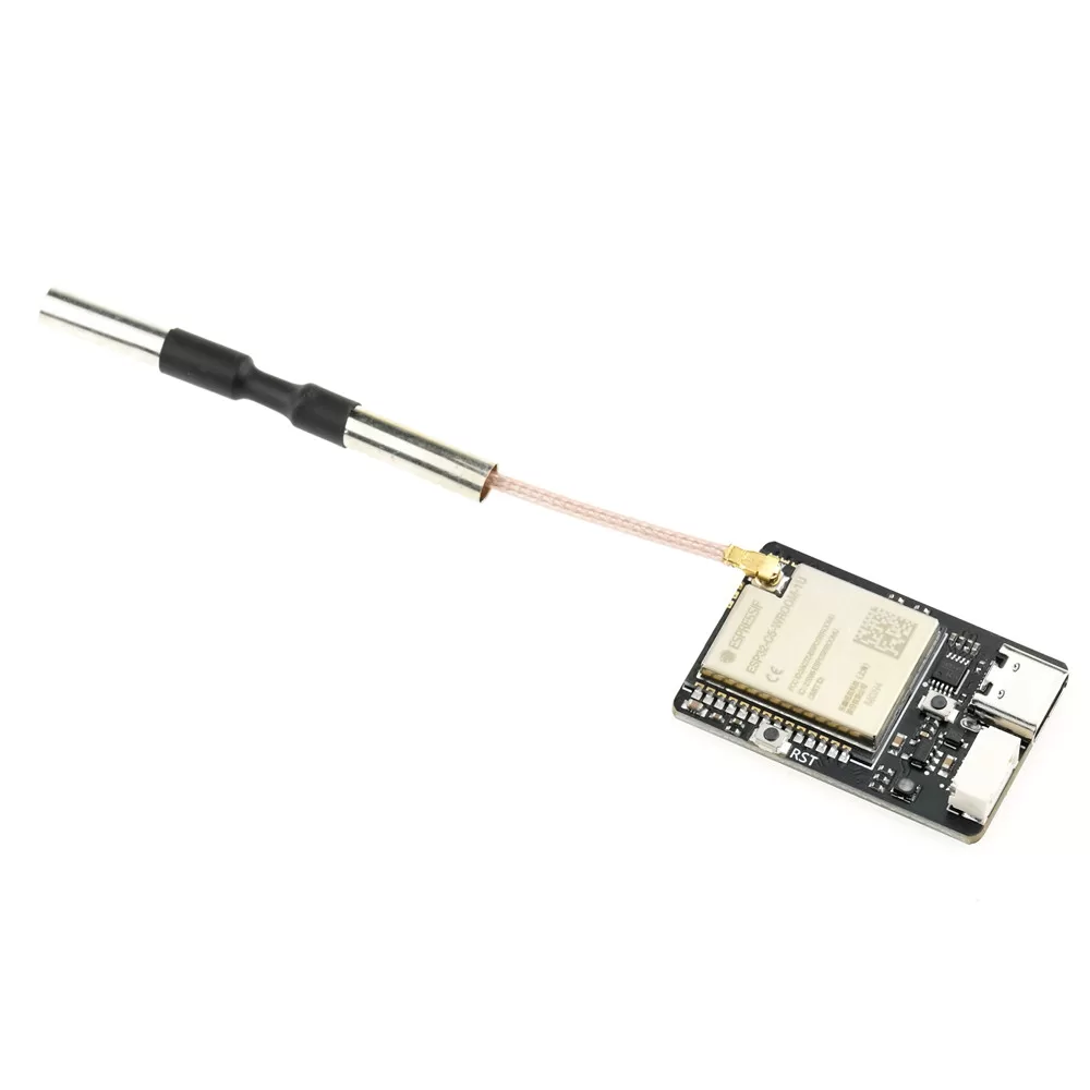
The MicoAir WiFi Link is a dual-band WiFi 6 telemetry module built for wireless data links on drones and robots. It gives an ArduPilot or PX4 flight controller a wireless MAVLink connection to your ground station — no USB cable to the aircraft — and its OFDMA and downlink MU-MIMO support keeps connections reliable when many aircraft share one network, which is exactly what drone-swarm and light-show setups need.
Where to buy
- Robofusion store (ships from Canada — free Canada-wide shipping): MicoAir WiFi Link — Dual-Band WiFi 6 Telemetry Module
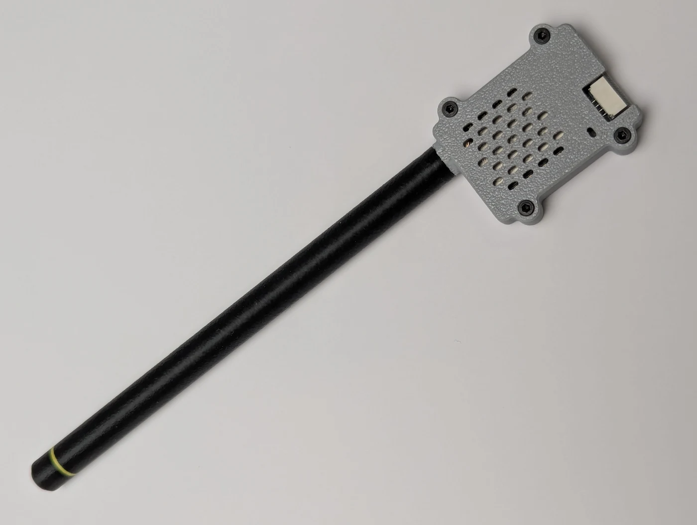
The WiFi Link ships as a bare board with a bare antenna. Robofusion has designed a free 3D-printable protective case for the module and a matching antenna radome — shown above as printed. Both downloads include the model files and print profiles:
- Download on MakerWorld — print straight from the MakerWorld profile.
- Direct download (ZIP) — all model and print-configuration files in one package.
What is it for?
Typical applications:
- Wireless ArduPilot / PX4 tuning — connect over WiFi from ground-station software such as Mission Planner, QGroundControl (QGC) and MicoPilot, instead of plugging in a USB cable.
- Drone-swarm and light-show networking — multi-drone communication, waypoint upload and command upload over one LAN (works with Skybrush). See the multi-drone networking tutorial.
- Robotics and unmanned-system wireless access — any control or debugging scenario that needs a short-range, high-bandwidth wireless serial link.
Key features
- Powered by the ESP32-C5
- Dual-band WiFi: 2.4 GHz / 5 GHz
- WiFi 6 (802.11ax), backward compatible with 802.11 a/b/g/n/ac
- Ships in AP mode — your PC or phone connects straight to the module's own hotspot
- STA mode for joining an existing router (the basis for multi-drone networking)
- Bidirectional Serial ↔ UDP transparent transmission
- BLE serial transparent transmission (currently supported by the MicoPilot app only)
- Built-in web configuration page
- Full parameter configuration over USB serial AT commands
- Firmware upgrades via MicoAssistant
Specifications
| Item | Specification |
|---|---|
| Main controller | ESP32-C5 |
| Wireless standard | WiFi 6 / 802.11ax, backward compatible with 802.11 a/b/g/n/ac |
| Frequency bands | 2.4 GHz / 5 GHz |
| Communication interfaces | LVTTL (3.3 V) serial / USB Type-C (CH340) |
| Core functions | WiFi UDP serial transparent transmission / BLE serial transparent transmission (BLE currently supported by MicoPilot only) |
| Default WiFi mode | AP (switchable to STA via AT commands) |
| Max range, AP mode | 100 m (direct to phone/PC; open environment, no interference) |
| Max range, STA mode | 500 m (relayed via high-power router; open environment, no interference) |
| Max range, BLE | 10 m |
| Operating voltage | 5 V |
| Average operating current | 150 mA |
| Dimensions | 34.5 × 23.5 × 6 mm |
| Weight | 5.5 g (without antenna) |
Serial ports
| Port | Baud rate |
|---|---|
| Debug port (USB-C) | 115200 |
| Telemetry port | 57600 / 115200 (default) / 230400 / 460800 / 921600 |
The telemetry port defaults to 115200. The flight-controller serial port it's wired to must be set to the same baud rate, or nothing will communicate.
Default network parameters
| Parameter | Default |
|---|---|
| AP SSID | MicoAir_WiFi_Link_XXXX |
| AP password | 12345678 |
| AP gateway (config page address) | 192.168.4.1 |
| STA local IP | 192.168.1.101 |
| STA target IP | 192.168.1.2 |
| STA gateway | 192.168.1.1 |
| UDP port | 14550 |
Anyone within range can join an open default hotspot. Once you're up and running, change the AP password (see AT example 4).
WiFi operating modes
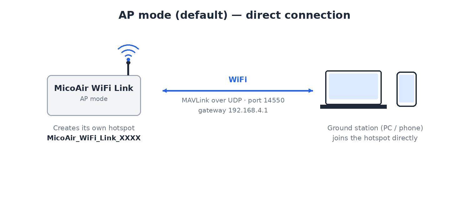
AP mode (default) — the module creates its own WiFi hotspot and the ground station (PC or phone) connects directly to it. Zero network setup: power the module, join its hotspot, connect your GCS.
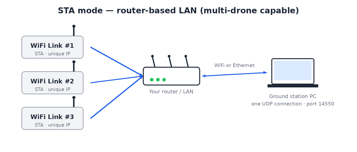
STA mode — the module joins an existing router as a client, and the ground station communicates with it inside the same LAN. This extends range (through the router) and is how you connect multiple aircraft to one ground station — see the multi-drone networking tutorial.
BLE
- Bluetooth name:
MicoAir_BLE_XXXX - Bluetooth password: none
- Range: ~10 m
- Supported by: currently only the MicoPilot GCS app connects to the flight controller over this BLE link.
BLE and 2.4 GHz WiFi share one physical antenna and channel, so only one can be active at a time. Factory default is 5 GHz WiFi (AP mode) + BLE. Switching the module to 2.4 GHz WiFi (AP mode) automatically disables BLE; in STA mode, joining a 2.4 GHz router also disables BLE.
Interfaces and wiring
Telemetry (serial) interface
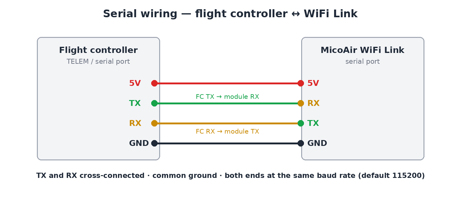
Three rules cover almost every wiring problem:
- TX and RX must be cross-connected (module TX → FC RX, module RX → FC TX).
- The flight controller and the module must share a common ground (GND).
- The flight-controller serial baud rate must match the module's configured baud rate (115200 by default).
Debug interface (USB-C)
The module's USB Type-C serial port is used for:
- configuring parameters via AT commands, and
- firmware upgrades via MicoAssistant.
Default debug-port settings: 115200 baud / 8 data bits / 1 stop bit / no parity.
The USB serial chip is a CH340 — if the module doesn't show up as a COM port on Windows, install the driver: CH340 Windows driver download.
Web configuration
In AP mode, join the module's hotspot and open a browser at:
http://192.168.4.1
Here you can configure basic WiFi parameters.
Switching to STA mode is currently only supported through AT commands, not the web page.
AT command reference
The module accepts AT commands over the USB serial port (115200 baud).
Append a carriage return + line feed (\r\n) to every command. In a PC serial monitor, tick "Append CR-LF" / "Send Newline" in the settings.
| Command | Description |
|---|---|
AT | Test communication; returns OK |
AT+ALL? | Query all current configuration |
AT+STATUS? | Query current network state and core parameters |
AT+MODE? / AT+MODE=<0/1> | Query / set operating mode (0: AP, 1: STA) |
AT+BLE? / AT+BLE=<0/1> | Query / set BLE telemetry (0: off, 1: on) |
AT+CHAN? / AT+CHAN=<1~14> | Query / set the 2.4 GHz WiFi channel (AP mode only) |
AT+APSSID? / AT+APSSID=<ssid> | Query / set the module's own AP hotspot name (max 32 chars) |
AT+APPWD? / AT+APPWD=<pwd> | Query / set the AP hotspot password (8–63 chars) |
AT+SSID? / AT+SSID=<ssid> | Query / set the target router SSID (STA mode) |
AT+PWD? / AT+PWD=<pwd> | Query / set the target router password (STA mode) |
AT+BAUD? / AT+BAUD=<baud> | Query / set the telemetry serial baud rate |
AT+PORT? / AT+PORT=<port> | Query / set the UDP port (default 14550) |
AT+MIP? / AT+MIP=<ip> | Query / set the module's local static IP |
AT+GW? / AT+GW=<ip> | Query / set the gateway IP (with static IP in STA mode) |
AT+TIP? / AT+TIP=<ip> | Query / set the target (ground-station PC) IP |
AT+VER? | Query firmware version |
AT+RST | Reboot the module (required after changing parameters) |
AT+RESET | Restore factory defaults |
AT+CHAN accepts 1–14, but not every channel in that range is legal everywhere. Channels 12 and 13 are not permitted for normal use in the United States and are restricted in Canada, and channel 14 is Japan-only. In North America, stay on channels 1–11.
AT command examples
The module replies OK after successfully executing a command.
Example 1 — query current state and parameters
Send: AT+STATUS?
Typical response:
Mode: AP
AP_SSID: MicoAir_WiFi_Link_ABCD
AP_PWD: 12345678
IP: 192.168.4.1
Baud: 115200
UDP_Port: 14550
Target_IP: 255.255.255.255
OK
Example 2 — change the telemetry baud rate
To run the FC ↔ module link at a higher rate (e.g. 460800):
Send: AT+BAUD=460800
Response: OK

Send: AT+RST
Response: OK
The new baud rate takes effect after reboot — use it for future AT communication, and set the flight-controller serial port to the same value.
Example 3 — switch to STA mode and join a router
To extend range or put several devices on one LAN, configure the module as a client (STA) of an existing router (example: SSID MyRouter, password password123):
1. Target router SSID
Send: AT+SSID=MyRouter
Response: OK

2. Target router password
Send: AT+PWD=password123
Response: OK

3. Static IP for the module (unique per module, no LAN conflicts)
Send: AT+MIP=192.168.1.101
Response: OK

4. Target (ground-station PC) IP
Send: AT+TIP=192.168.1.200
Response: OK

5. Switch to STA mode (mode ID 1)
Send: AT+MODE=1
The module reboots automatically to apply.
For the full multi-aircraft procedure, follow the multi-drone networking tutorial.
Example 4 — change the default AP password
In the factory-default AP mode, change the AP password to keep others off your link (minimum 8 characters):
Send: AT+APPWD=my_new_pwd
Response: OK

Send: AT+RST
Response: OK
After reboot, clients joining the module's hotspot must enter the new password.
Connecting a ground station
First make sure the module is wired to a flight-controller serial port and that port's baud rate is set to 115200 (the WiFi Link default).
MicoPilot (mobile)
-
BLE: enable Bluetooth on the phone, open MicoPilot, tap Connect (top right) and choose Bluetooth. The device list appears automatically — the module shows up as
MicoAir_BLE_XXXX, usually in the first row. Tap it to connect.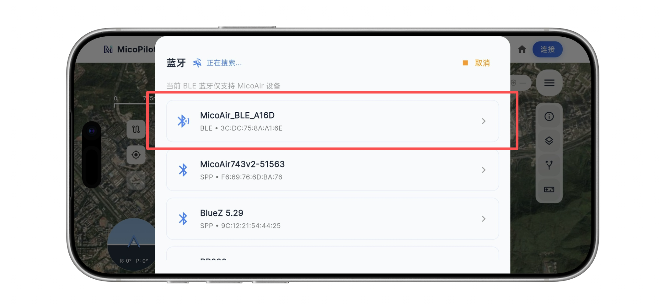
-
WiFi UDP: join the module's hotspot (
MicoAir_WiFi_Link_XXXX) from the phone first. Open MicoPilot, tap Connect, choose WiFi/UDP, select UDPCI, keep the default gateway IP192.168.4.1and port14550, and tap connect.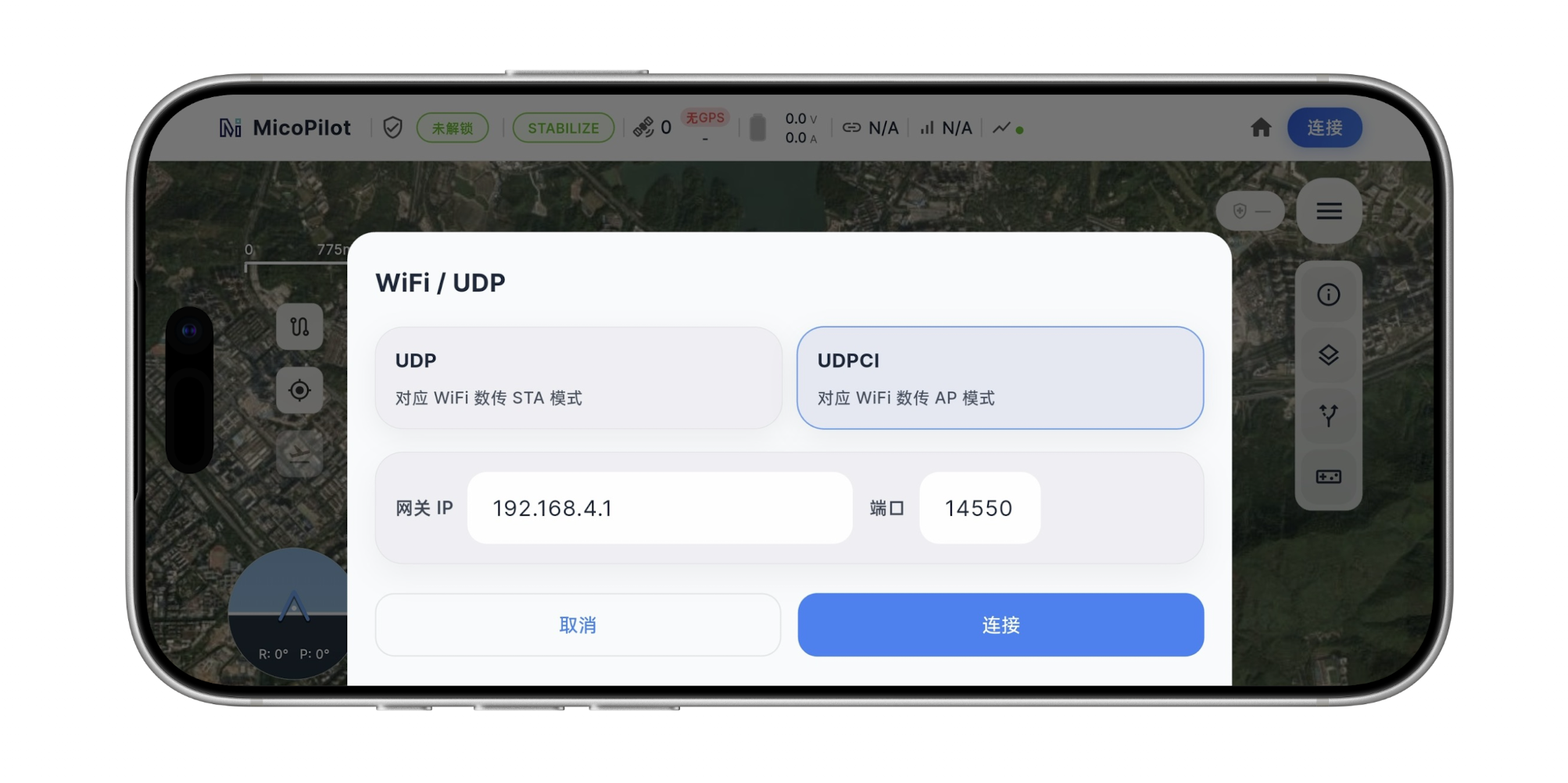
Mission Planner (AP mode)
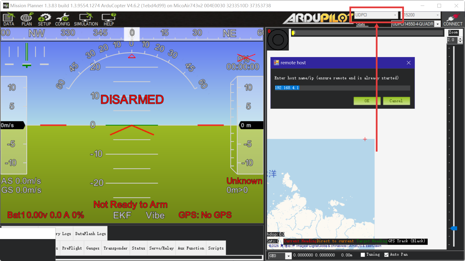
In the top-right corner of Mission Planner, select UDPCI as the connection type and click Connect. In the dialog, enter the module's gateway IP 192.168.4.1 and port 14550 — Mission Planner will connect to the flight controller automatically. If it can't connect or fetch parameters, check that your PC is on the module's WiFi, the FC serial baud rate is 115200, and TX/RX are cross-connected.
QGroundControl
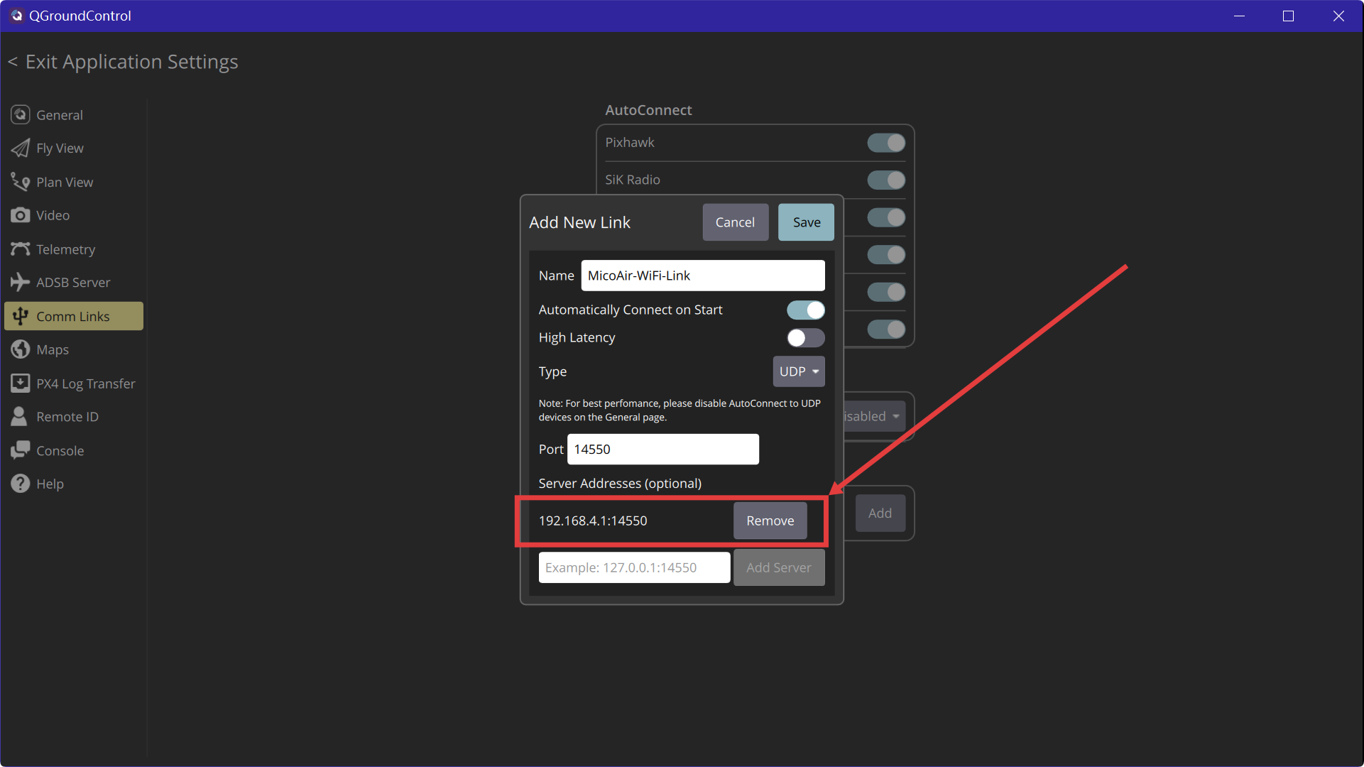
Open QGC → Application Settings → Comm Links → Add. Set Type to UDP, Port to 14550, add the module's gateway IP 192.168.4.1 under Server Addresses, tick Automatically Connect on Start, and Save. Enable UDP under AutoConnect, then select the link and click Connect. If it still won't connect, turn off the Windows firewall or whitelist QGC in it.
Easily confused points
AT+MIP and AT+TIP point in opposite directions. AT+MIP is the module's own address on the LAN; AT+TIP is the address of the ground-station computer it should send data to. Swapping them produces a module that joins the network perfectly and delivers telemetry to nobody.
Changing AT+BAUD changes the rate you must talk to the module at. After the reboot, further AT commands have to be sent at the new rate — not at 115200. Set the flight-controller serial port to match at the same time, or you will have moved the mismatch rather than fixed it.
The web page cannot switch the module to STA mode. It handles basic WiFi parameters only; the mode switch is an AT command. This is the usual reason a first STA attempt appears to do nothing.
Nothing takes effect until the module reboots. AT+RST after changing parameters — except AT+MODE, which reboots the module by itself.
AT+RST and AT+RESET are one letter apart and do opposite-sized things. AT+RST reboots. AT+RESET wipes every setting back to factory. Read twice before pressing enter.
BLE and 2.4 GHz WiFi cannot both be on. They share one antenna and channel. The factory configuration is 5 GHz AP + BLE, and moving the module to 2.4 GHz — in AP mode or by joining a 2.4 GHz router in STA mode — silently disables Bluetooth.
The AP gateway address is not a LAN address. 192.168.4.1 is the module's own hotspot gateway in AP mode. In STA mode the module has whatever address AT+MIP gives it on the router's subnet, and 192.168.4.1 is meaningless.
FAQ
Does it work with Mission Planner and QGroundControl?
Yes — the module streams MAVLink over UDP (default port 14550), which both Mission Planner (UDPCI) and QGC (UDP comm link) support. BLE, on the other hand, currently works only with the MicoPilot app.
What's the real-world range?
About 100 m in AP mode (direct to phone/PC) and up to 500 m in STA mode through a high-power router — both figures from open, interference-free test environments. Buildings, carbon frames and busy RF environments reduce this.
Ground station can't see the flight controller — what do I check first?
In order: is the PC/phone actually on the module's WiFi hotspot; is the FC serial port set to 115200 (or whatever AT+BAUD is set to); are TX/RX cross-connected with a common ground.
How do I update the firmware?
Over USB-C with MicoAssistant.
Related guides
- MicoAir WiFi Link — Multi-Drone Networking Tutorial
- ArduPilot — Telemetry Setup Guide
- PX4 — Telemetry Setup Guide
Written and maintained by the Robofusion engineering team.