RTK Setup Guide — From Unboxing to RTK FIXED
This tutorial takes a MicoAir MA-RTK-BASE and any MA-RTK-AIR rover (982 / 626 / F9P) from the box to a centimeter-accurate RTK FIXED solution, on ArduPilot or PX4. It assumes the rover is already wired and configured per the series user manual; background concepts live in the plain-English RTK explainer.
The two ways corrections can reach your drone
The base station produces RTCM correction data; the only design decision is how that stream gets to the rover:
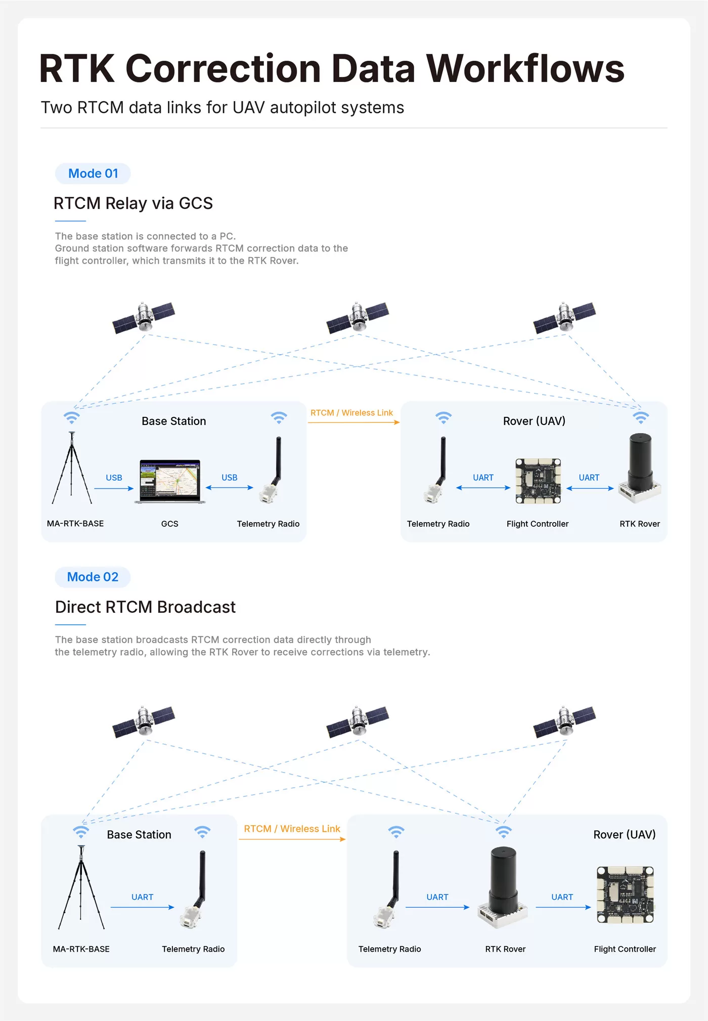
| Mode 1 — GCS relay | Mode 2 — direct radio broadcast | |
|---|---|---|
| Path | Base → USB → laptop GCS → existing telemetry link → FC → rover | Base → UART → radio → radio → rover 4P port |
| Extra hardware | none (reuses your telemetry) | one extra radio pair (e.g. LR900-F) |
| Needs a laptop running all mission | Yes | No — fully standalone |
| Shares telemetry bandwidth | Yes | No |
| Ground station | Mission Planner or MicoConfigurator — not QGC | any, including QGC |
| Best for | mapping days where a GCS is open anyway | light shows, swarms, long deployments |
Swarm note: in Mode 2 one radio broadcast serves every drone in range — each aircraft just needs a receiver radio on its rover's 4P port. In Mode 1, MAVLink-routed corrections reach each vehicle individually through their telemetry links.
Step 1 — Deploy the base station
-
Pick the spot. Widest sky view you can get: away from buildings, tree lines and metal roofs, elevated if possible. Every satellite the base can't see is a satellite your rovers can't use in the RTK solution.
-
Set up the tripod, screw the mushroom antenna on top, and connect it to the base's SMA port with the feeder cable.
-
Power on — hold the power button on the underside. The base starts working on its own and reports progress on the OLED; there is nothing to configure.
-
Wait for
RTK BASE. The screen walks through three states:OLED status What it means NO FIXEDjust powered up, still initialising — leave it completely still 3Dordinary 3D position fix; satellite count and HDOP now show on screen RTK BASEsettled and emitting RTCM — this is the state you need In genuinely open sky this takes a few minutes. The base emits RTCM3 on both the USB-C port and the GH1.25-4P UART simultaneously, at 115200 baud, 1 Hz.
-
Don't move it. The base averages its own position after power-up ("survey-in"); relocating, tilting or re-levelling it mid-session shifts every rover's frame. Runtime on internal batteries is ≈ 12 h — for all-day-plus operation feed it 5 V/2 A over USB-C.
The self-surveyed base position is itself only meter-accurate, so all rover positions share that same constant offset. For mapping against real-world coordinates, either post-shift your outputs using a known point, or program the base's true surveyed coordinates with Unicore's UPrecise tool. For light shows, precision landing and any "repeatability" job, the offset is irrelevant.
Step 2, Mode 1 — Relay corrections through the ground station
Mission Planner (ArduPilot)
- Connect the base to the laptop with the USB-C cable. Windows needs the CH340 driver (chip in the base's USB port) — if no COM port appears in Device Manager, install the CH340 driver and replug.
- Connect Mission Planner to your vehicle over telemetry as usual.
- Open Setup → Optional Hardware → RTK/GPS Inject.
- In the top-left dropdown pick the base's COM port, set baud 115200, click Connect.
- The status panel starts counting RTCM messages and shows the satellites the base sees. Mission Planner now wraps the RTCM into
GPS_RTCM_DATAMAVLink messages and injects them through the telemetry link — no vehicle-side setting needed. - Watch the HUD GPS status walk up: 3D Fix → RTK Float → RTK Fixed (typically well under 2 minutes in open sky).
MicoConfigurator (ArduPilot or PX4)
MicoConfigurator has a dedicated RTK page in its left-hand navigation:
- Get the rover to a normal 3D fix first, and make sure MicoConfigurator is connected to the flight controller (over USB or over a telemetry link) and reading parameters reliably. If the vehicle link itself is shaky, corrections will not get through either.
- Plug the base into the computer with the USB-C cable.
- Open the RTK page, set the base serial rate to 115200 and click Connect, then pick the base's COM port.
- The page starts parsing RTCM and forwarding it to the connected vehicle automatically.
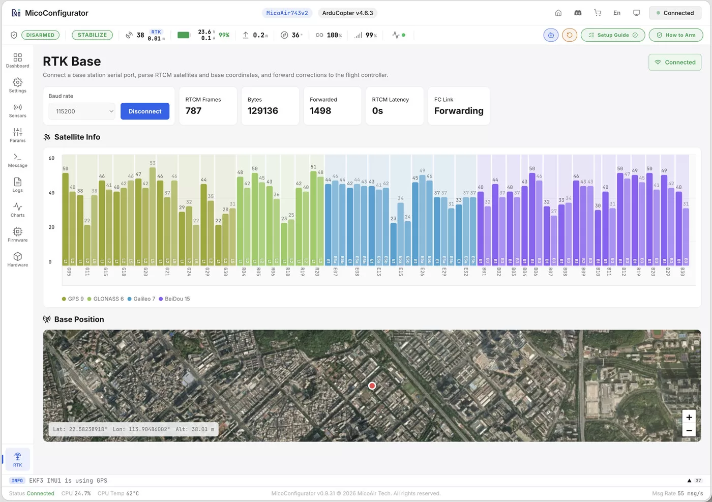
The computer has to stay running, connected to both the base and the vehicle, for as long as you want RTK.
QGC's RTCM forwarding does not currently work with the MA-RTK-BASE. Use Mission Planner or MicoConfigurator for the relay path — or skip the relay entirely and use the direct radio broadcast below, which works no matter what ground station you fly with, QGC included.
Step 2, Mode 2 — Broadcast corrections over a telemetry radio
Fully standalone: no laptop after setup. The corrections never touch the computer or the flight controller — they go straight into the rover, which hands the flight controller a finished position.
An LR900 pair ships in duplex mode at 57600 baud, which is correct for flight-controller telemetry and wrong for this job. Correction broadcast is one-way, so the two radios have to be set to different work modes — one transmits, the other receives — before anything will flow. Configure both with MicoAssistant before you wire them up.
Radio settings (both radios, using MicoAssistant):
| Parameter | Ground radio (at the base) | Air radio (at the rover) |
|---|---|---|
| Work mode | Broadcast-transmit | Broadcast-receive |
| Serial baud rate | 115200 | 115200 |
| Module address | the same on both | the same on both |
| Frequency point / mode | the same on both | the same on both |
| Data rate | the same on both | the same on both |
115200 is the base's output rate, the rover's default port rate, and also the LR900's highest serial setting — which is ample for a 1 Hz RTCM stream.
Ground side: connect the base's GH1.25-4P UART (GND·VCC·TX2·RX2) to the ground radio — base TX2 → radio RX, base RX2 → radio TX. The base powers the radio from the same connector. Fit the antenna before powering up.
Air side: connect the air radio to the rover's GH1.25-4P port the same way (radio TX → rover RX2). Check this twice: the air radio goes to the rover module's 4P port, not to a flight-controller serial port. The rover ingests RTCM there automatically and the flight controller needs no extra parameters at all.
One ground radio broadcasts to any number of air radios on the same address and channel — which is exactly why this is the mode light shows and swarms use.
The rover simply eats RTCM from whichever source delivers it — GCS relay via the FC, or the 4P port. Don't run both simultaneously for the same vehicle; pick one path per session.
Step 3 — Confirm RTK FIXED
The single most reliable thing to watch is GPS_RAW_INT.fix_type, which is the same number whatever ground station you use:
fix_type | Meaning |
|---|---|
| 3 | ordinary 3D fix — corrections are not reaching the rover |
| 5 | RTK Float — corrections are arriving and being used, ambiguities not yet resolved |
| 6 | RTK Fixed — full centimetre solution |
- Mission Planner: HUD shows
RTK Fixed; in the status tabgpsstatusreads 6 (5 = FLOAT). Horizontal accuracy (gpshacc) settles to centimetres. - QGroundControl: toolbar GPS indicator reads
RTK Fixed. - Expect FLOAT within ~30 s of corrections flowing and FIXED shortly after in open sky. Stuck in FLOAT → see troubleshooting.
Prove the link end to end. Once you are at 5 or 6, interrupt the corrections deliberately — stop the forwarding in MicoConfigurator, or switch off the ground radio — while leaving the base, rover and flight controller powered. Wait for the fix type to drop back to 3, then restore the link. If it climbs back to 5 or 6 on its own, the whole chain is genuinely working rather than coasting on a stale solution.
Which segment is broken? Work along the path of the data:
| Symptom | The segment to check |
|---|---|
| RTCM received count never increases | Base → computer: is the base showing RTK BASE, is the CH340 COM port right, is the rate 115200 |
| Received count rises, forwarded count doesn't | Computer → flight controller: the vehicle link itself |
Both counts rise, fix_type stays 3 | Flight controller → rover: the rover's wiring and configuration, and the sky view at both ends |
Dual-antenna GNSS heading (982)
The MA-RTK-AIR-982 Dual-Antenna Kit measures true heading from the geometry of its two antennas — no magnetometer involved, so motor current, steel structures and geomagnetic storms can't touch it.

Mounting rules:
- ANT1 is the primary antenna, ANT2 the secondary. Their arrangement is up to you — the two can sit side by side at the back of the frame, fore and aft along the centreline, or anywhere else — because what the firmware actually uses is the offset you measure, not a fixed layout. What matters is that you measure it correctly and that it never changes.
- Baseline (antenna separation) ≥ 20 cm — a longer baseline gives finer heading resolution.
- Keep both antennas at the same height where you can, both with clean sky view, both rigidly mounted. If the two can shift relative to each other in flight, the heading moves with them.
- Secure the feeder cables so they cannot tug an antenna out of position.
- Before configuring, measure the displacement from ANT2 to ANT1 along the three body axes: X forward, Y right, Z down.
ArduPilot:
GPS1_TYPE      = 25     # UnicoreMovingBaselineNMEA
GPS1_RATE_MS   = 100    # 10 Hz
GPS1_MB_TYPE   = 1      # RelativeToCustomBase
GPS1_MB_OFS_X  = ...    # ANT2 -> ANT1, forward positive, metres
GPS1_MB_OFS_Y  = ...    # ANT2 -> ANT1, right positive, metres
GPS1_MB_OFS_Z  = ...    # ANT2 -> ANT1, down positive, metres
EK3_SRC1_YAW   = 2      # EKF yaw from GPS
Set GPS1_MB_TYPE first — the three offset sub-parameters only appear once it is set, so refresh parameters or reconnect if you don't see them.
The offsets are the components of the ANT2 → ANT1 vector on each body axis, not the straight-line distance between the antennas. With the two antennas level and 30 cm apart:
| ANT1 relative to ANT2 | X | Y | Z |
|---|---|---|---|
| directly ahead | 0.30 | 0 | 0 |
| directly behind | −0.30 | 0 | 0 |
| directly to the right | 0 | 0.30 | 0 |
| directly to the left | 0 | −0.30 | 0 |
Mounted diagonally? Measure fore-aft, left-right and up-down separately — never put the diagonal distance into a single axis.
Optionally also set GPS1_POS_X/Y/Z, which is ANT1's position relative to the centre of gravity — a different measurement that improves position quality when the vehicle yaws on the spot. Leave it at 0 if you can't measure it accurately.
GPS1_MB_TYPE and GPS1_MB_OFS_X/Y/Z are the 4.6-and-later spelling. On 4.5 and earlier the same parameters are GPS_MB1_TYPE and GPS_MB1_OFS_X/Y/Z — the instance number moves. Likewise GPS1_POS_X/Y/Z was GPS_POS1_X/Y/Z. If a search finds nothing, try the other spelling before concluding your firmware can't do it.
Write everything, then reboot. You may afterwards set COMPASS_USE = 0 to drop the magnetometer entirely, or keep it as a fallback source (EK3_SRC2_YAW).
PX4:
GPS_1_PROTOCOL = 6      # NMEA (generic)
SER_GPS1_BAUD  = 230400 # or Auto
EKF2_GPS_CTRL           # tick bit 3, "Dual antenna heading"
GPS_YAW_OFFSET          # baseline angle from the nose, degrees
PX4 doesn't want a baseline length — only the angle of the ANT2 → ANT1 baseline relative to the nose, measured clockwise when viewed from above:
| ANT1 relative to ANT2 | GPS_YAW_OFFSET |
|---|---|
| directly ahead | 0 |
| directly to the right | 90 |
| directly behind | 180 |
| directly to the left | 270 |
Reboot after writing.
Check the heading actually works
Do this on the ground, in open sky, before you fly it.
1 — Is the module producing a heading at all? Look at GPS_RAW_INT.yaw in your ground station's MAVLink message inspector:
- 65535 — no dual-antenna heading available. Nothing downstream can work until this changes.
- a changing, sensible number — the module has a heading. The field is in hundredths of a degree, so
9000is 90° and18000is 180°.
2 — Does it point the right way? Aim the nose at something whose direction you know (a phone compass held with its top along the nose works), and compare with the heading your ground station shows. Then rotate the airframe about 90° clockwise — the displayed heading should increase by about 90°. Check near 0°, 90°, 180° and 270°, then turn back to the start; the heading should return and sit rock-steady while stationary.
Heading accuracy scales with baseline — with the kit's antennas at 20–30 cm, expect well under 1° once in RTK.
Troubleshooting
| Symptom | Likely cause → fix |
|---|---|
| Base COM port never appears | CH340 driver missing → install, replug |
| RTK Inject connects but 0 RTCM messages | Wrong COM port or baud ≠ 115200; base PVT LED not solid yet (no fix → no corrections) |
| Rover stuck in RTK Float | Marginal sky at base or rover (multipath) → move base, raise rover antenna; weak radio link → shorten distance, check antennas; very long baseline → move base closer |
| FIXED drops in flight | Correction link dropping — telemetry bandwidth saturated (Mode 1: lower stream rates or switch to Mode 2) or radio range exceeded |
Radios linked but fix_type never leaves 3 | Work modes not set: ground must be broadcast-transmit, air broadcast-receive; both radios need the same address, frequency and data rate; air radio must be on the rover's 4P port, not an FC serial port; check Tx/Rx crossing at both ends |
GPS_RAW_INT.yaw stays 65535 | No dual-antenna heading: ANT2 not connected, an antenna without sky view, baseline under 20 cm, antennas able to move relative to each other, or the moving-baseline parameters not set / not rebooted |
| 982 shows position but no yaw | GPS1_TYPE still 24 (single) → set 25 and refresh; or GPS1_MB_TYPE never set to 1, so the baseline offsets were never applied |
| 626 not detected by ArduPilot | GPS_AUTO_CONFIG not 0 |
| Heading is out by exactly 90°, 180° or 270° | The baseline direction is entered wrong — recheck the ANT2 → ANT1 offsets (ArduPilot) or GPS_YAW_OFFSET (PX4) |
| Heading moves the opposite way to the vehicle | ANT1 and ANT2 are swapped, or the vector was entered from ANT1 to ANT2. It always runs from the secondary antenna to the primary |
| FIXED and FLOAT keep alternating | Correction latency or packet loss on the radio link; also check that base, rover and radios all have steady power, and look for a VTX or similar interferer near an antenna |
| Erratic position near structures | Multipath — RTK cannot fix reflections; add height, move away from walls |
FAQ
Can I fly RTK without any base station? Yes, via NTRIP: Mission Planner and QGC can pull RTCM from an internet caster (public network or paid service) and inject it exactly like Mode 1 — you need cell coverage at the field and a nearby reference station.
How many drones can one base + one radio serve? Unlimited — RTCM broadcast is one-way. Every rover in radio range gets the same corrections.
Does RTK still work if the correction link drops? The rover degrades gracefully: FIXED → FLOAT → normal GPS over a few seconds, and recovers automatically when corrections resume. Missions keep flying on ordinary GPS accuracy meanwhile.
Base and rover from different vendors? Fine — anything speaking RTCM3 interoperates.
Related pages
- MA-RTK Series User Manual — specs, wiring, per-model parameters
- What Is RTK? — plain-English explainer
- LR900 Telemetry Radio — User Manual — the broadcast-mode radio
- Shop: MicoAir RTK hardware at Robofusion — ships worldwide from Hong Kong
Written and maintained by the Robofusion engineering team.