LR24 2.4 GHz Telemetry Radio — User Manual
The LR24 is a series of long-range telemetry radios operating in the 2.4 GHz ISM band, built on LoRa spread-spectrum modulation with FHSS frequency hopping for strong interference resistance and high receive sensitivity. It provides a full-duplex transparent serial link between two points: an ArduPilot or PX4 flight controller and a ground station running Mission Planner or QGC — or any two serial devices, such as an RTK base and rover.
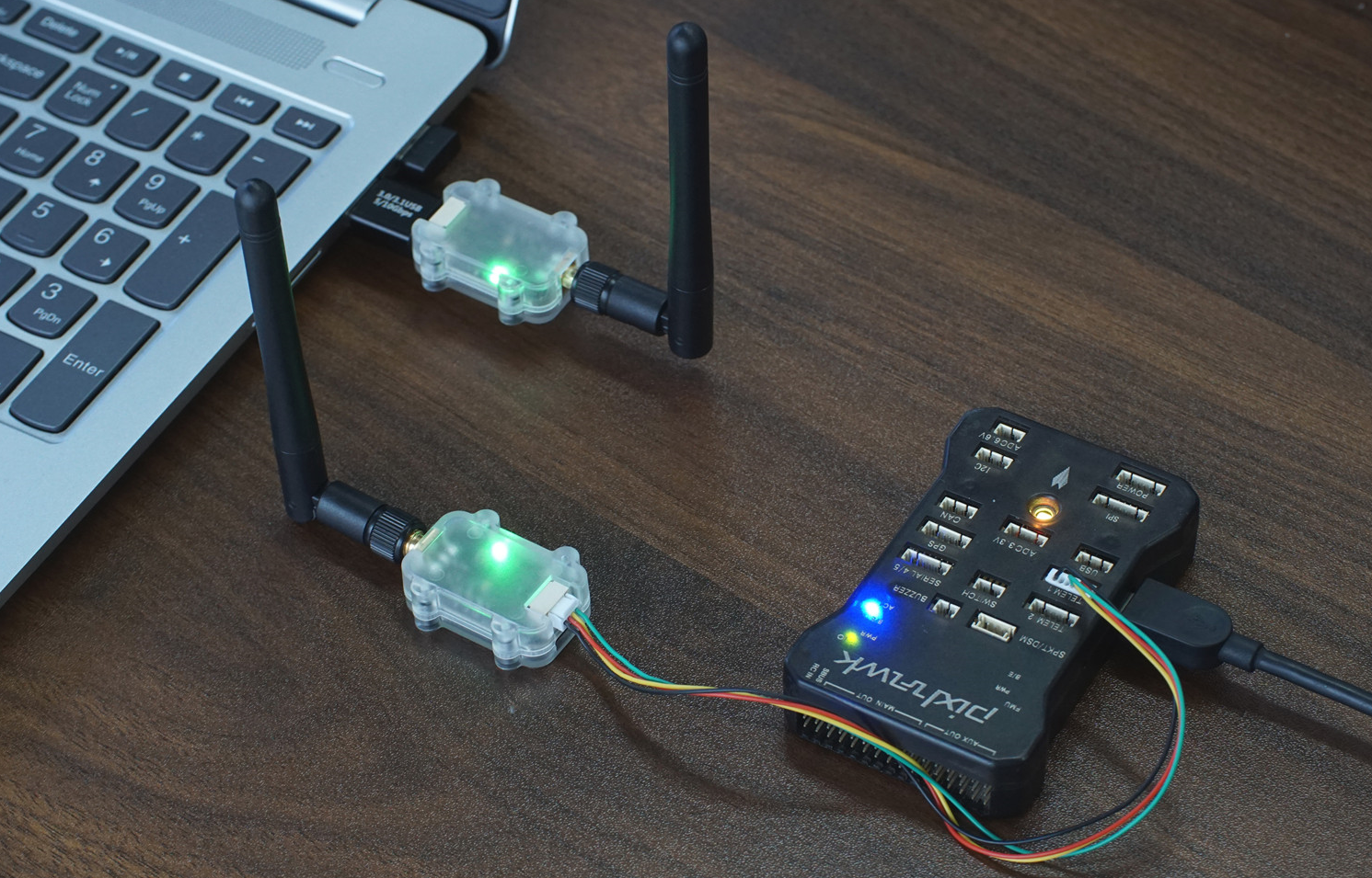
Where to buy
- Robofusion store (ships from Canada — free Canada-wide shipping): LR24-F 2.4GHz Telemetry Radio (pair)
- Amazon (US): LR24-F on Amazon
Which model? (F vs P vs F-Mini)
| Model | Max Tx power | Case | USB-C / USB chip | Serial connector | Weight |
|---|---|---|---|---|---|
| LR24-P | 30 dBm (1000 mW) | Yes | Yes / CP2102 | GH1.25-4P | 8 g |
| LR24-F | 27 dBm (500 mW) | Yes | Yes / CP2102 | GH1.25-4P | 8 g |
| LR24-F-Mini | 27 dBm (500 mW) | Bare board | None | SH1.0-4P | 2.5 g |
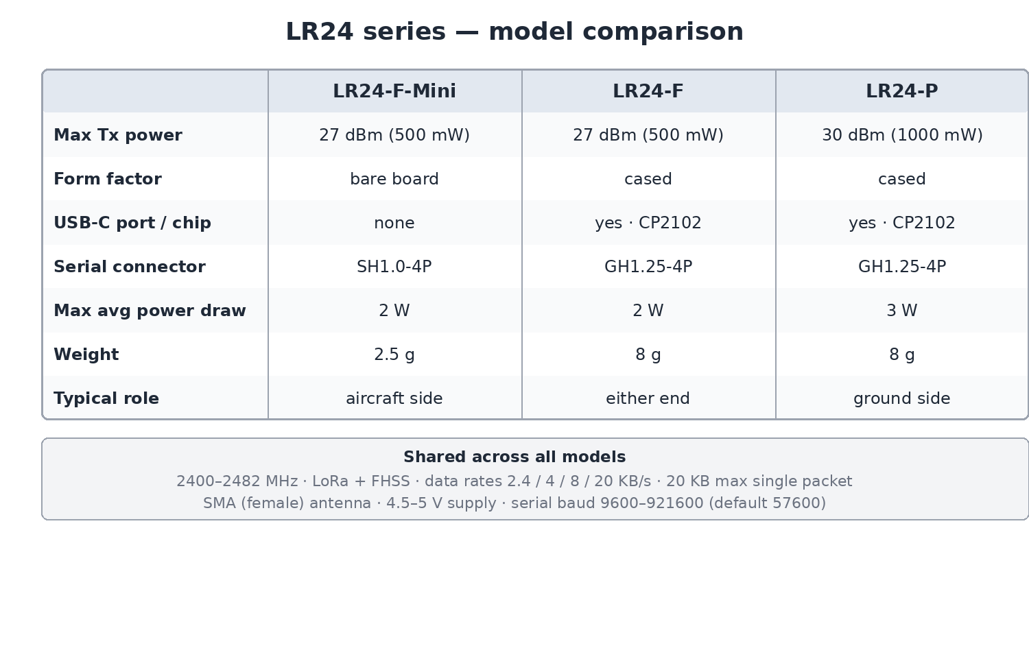
Two notes on reading the chart:
- Data rate is the transparent (over-the-air) throughput of the duplex link, shared by both directions. The 20 KB/s mode switches to FLRC modulation, and the higher modes require matching serial baud rates — see the caution below.
- Communication range follows the lower-power end of a link: any model pairs with any other, but an LR24-P talking to an LR24-F effectively has LR24-F range. Quoted figures assume open, interference-free conditions with the stock antennas.
Three practical rules:
- Any model pairs with any model — but the usable range is set by the lower-power end of the link.
- A common combination: LR24-P on the ground (power is cheap there) and LR24-F-Mini on the aircraft (2.5 g, no case, no USB hardware you don't need in the air).
- The F-Mini has no USB port — to configure it, wire its serial port to a USB-TTL adapter, or configure its parameters while temporarily connected through another radio's setup. The F and P configure directly over their own USB-C.
Specifications
| Item | Specification |
|---|---|
| Frequency band | 2400–2482 MHz (2.4 GHz ISM) |
| Modulation | LoRa spread spectrum (FLRC in the 20 KB/s mode) + FHSS hopping |
| Tx power | 1000 mW (LR24-P) / 500 mW (LR24-F, F-Mini) |
| Transparent data rates | 2.4 KB/s (default) / 4 KB/s / 8 KB/s / 20 KB/s |
| Max serial single-packet length | 20 KB |
| Interfaces | LVTTL (3.3 V) serial; USB Type-C (F/P only) |
| Serial baud rate | 9600–921600, default 57600 |
| Antenna connector | SMA (female) |
| Supply voltage | 4.5–5 V |
| Max average power draw | 3 W (LR24-P) / 2 W (LR24-F, F-Mini) |
| Weight | 8 g (F/P) / 2.5 g (F-Mini) |
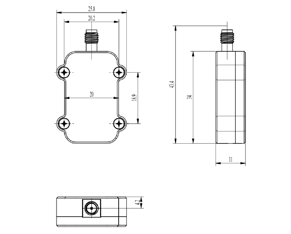
Mechanical drawings — LR24-F/P (3D model, STP):
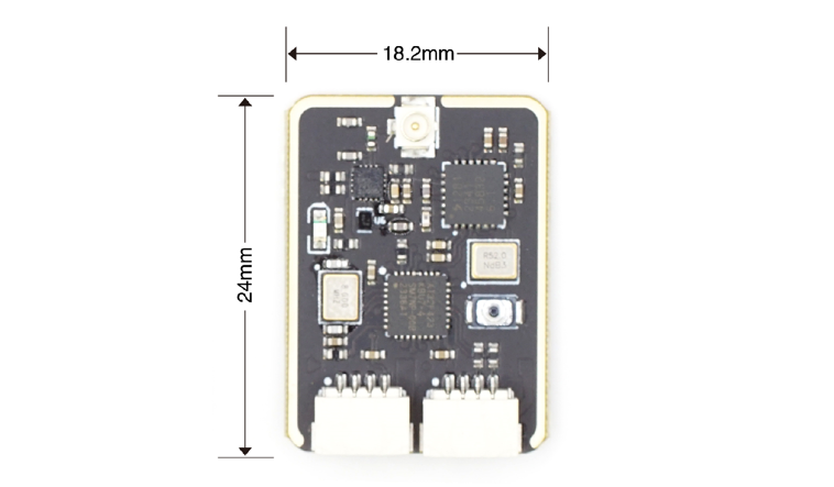
LR24-F-Mini:
The LR24-P averages up to 3 W ≈ 600 mA at 5 V, and the F models up to 2 W ≈ 400 mA. Many flight-controller TELEM ports can't supply that. If in doubt, power the radio from a reliable external 5 V BEC and run only GND / TX / RX to the flight controller.
Interfaces and wiring
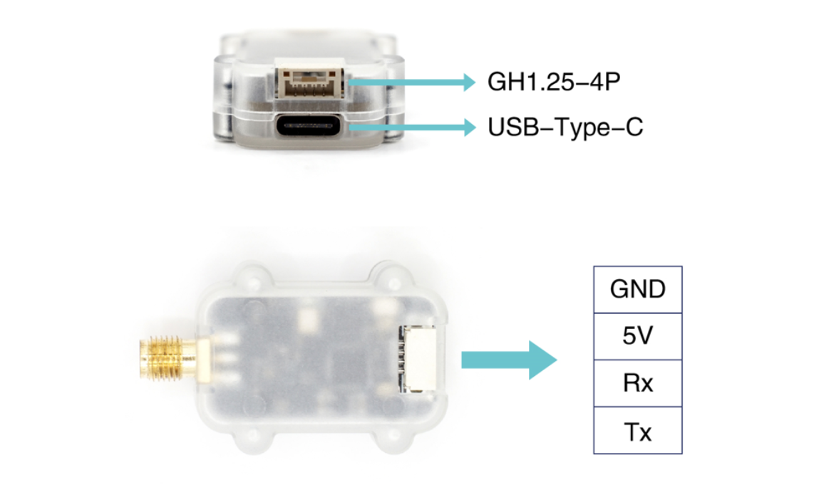
LR24-F / LR24-P have two external interfaces:
- A 3.3 V-level TTL serial port (GH1.25-4P) — this is what you wire to a flight-controller serial port.
- A USB Type-C port — for connecting to a computer only (configuration; requires the CP2102 driver). The USB port is not used to wire the radio to a flight controller.
LR24-F-Mini has a single interface — a 3.3 V TTL serial port (SH1.0-4P):
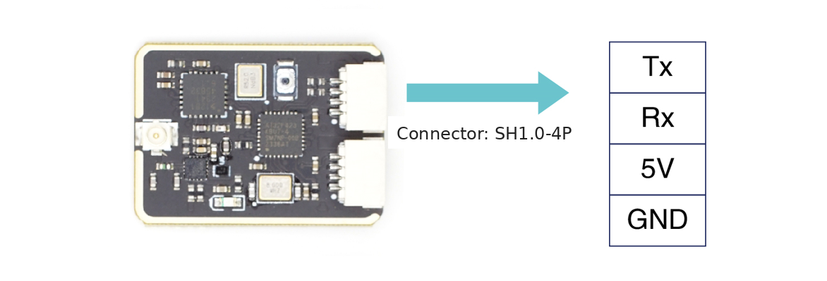
Pinout for all models — the same three rules as every telemetry radio:
| Pin | Connects to |
|---|---|
| Tx | flight controller serial Rx |
| Rx | flight controller serial Tx |
| 5V | 5 V supply |
| GND | ground (common with the flight controller) |
Configuration software and driver
Parameters are configured with MicoAssistant over the USB-C port (LR24-F/P).
Windows needs the USB-serial driver first — the LR24-F/P use the CP2102 chip: CP2102 Driver Installation (Windows).
LED indicator
The green LED shows link status:
- Blinking at 1 Hz — not connected
- Solid on — paired and linked
How pairing works
Two LR24 radios with identical parameters connect automatically at power-up — and factory-fresh units ship with identical defaults, so a new pair links out of the box with zero configuration.
Running several pairs in the same area? Give each pair its own Module Address so the pairs don't cross-talk (details below).
Parameters explained
Work Mode
Duplex (default) / Broadcast-TX / Broadcast-RX.
- Duplex — two-way link; the only mode to use for flight-controller telemetry.
- Broadcast-TX / Broadcast-RX — one-way send or receive, typically for RTK base → rover correction streams (one base transmitting to any number of listening rovers).
Data rate (transparent transmission speed)
Four over-the-air rates: 2.4 KB/s (default) / 4 KB/s / 8 KB/s / 20 KB/s. The 20 KB/s mode switches from LoRa to FLRC modulation; all other modes use LoRa.
Slower = farther. Pick the slowest rate your application tolerates.
- In the 8 KB/s mode, set the serial and USB baud rates to 115200 or higher.
- In the 20 KB/s mode, set them to 921600.
Leaving the default 57600 baud in those modes is the classic "configured a faster mode, now nothing works" mistake — the serial side simply can't carry what the radio side delivers.
Frequency mode
Manual / Auto (default) / FHSS-GROUND / FHSS-AIR.
- Auto — the link picks its channel automatically. Fine for bench work and simple links.
- FHSS — frequency hopping; recommended for flight-controller telemetry. Set the aircraft end to
FHSS-AIRand the ground end toFHSS-GROUND. - Manual — fixes the channel; only then does the Channel parameter apply.
Channel
Active in Manual frequency mode only. Values 0–82 map to 2400–2482 MHz (one channel per MHz).
Module Address
Default 1000, range 1–30000. Only radios with the same address can talk. Multiple pairs in one area → one unique address per pair.
Serial baud rate
The GH1.25/SH1.0 serial-port rate: 9600 / 19200 / 38400 / 57600 (default) / 115200 / 230400 / 460800 / 921600. Remember the data-rate coupling above — and the flight-controller port must match this value.
USB baud rate
The USB-C port rate (F/P): 57600 (default) / 115200 / 921600. Same data-rate coupling applies.
LR24 or LR900 — which band should you buy?
Both are LoRa+FHSS transparent serial radios with the same job; the band changes the trade-offs:
| LR900 (915 MHz) | LR24 (2.4 GHz) | |
|---|---|---|
| Band | 890–915 MHz | 2400–2482 MHz |
| Range character | Better penetration and diffraction — trees, terrain, buildings | Shorter reach through obstacles, more spectrum for speed |
| Top data rate | 2.1 KB/s | 20 KB/s |
| Max single packet | 4–8 KB | 20 KB |
| Plays well with | 2.4 GHz RC links (ELRS 2.4) | 915 MHz RC links (ELRS 915 / Crossfire) |
| Manual | LR900 User Manual | this page |
The last row is the one that bites people:
Don't run a 2.4 GHz RC receiver (e.g. ELRS 2.4G) and a 2.4 GHz LR24 telemetry radio on the same aircraft — two transmitters sharing a band at close quarters interfere. Sensible pairings: LR24 telemetry + 915 MHz RC, or LR900 telemetry + 2.4 GHz RC. If you'd rather not manage two links at all, the TRS system integrates RC control and telemetry into a single 2.4 GHz link.
Using it with a flight controller
The setup procedure is identical to other MicoAir transparent radios — follow:
The only LR24-specific note: the default serial baud is 57600 — either set the flight-controller port to 57600, or raise both sides together (required anyway for the 8/20 KB/s modes).
FAQ
Which model for the aircraft, which for the ground?
Typical split: F-Mini in the air (2.5 g, no unnecessary USB hardware), P on the ground (maximum power where weight is free). Any mix works; range follows the weaker end.
Two radios won't link — first checks?
Both powered, same Module Address, same data rate, compatible frequency modes (FHSS-AIR must face FHSS-GROUND), antennas attached. Factory-default pairs link automatically — if you changed parameters on one side only, that's the usual culprit.
Can I use the LR24 for RTK corrections?
Yes — that's what the broadcast modes are for: base in Broadcast-TX, rover(s) in Broadcast-RX.
Does the USB port connect to the flight controller?
No — USB-C is for computer configuration only. Flight-controller wiring always uses the TTL serial port.
Related guides
- LR900 Telemetry Radio — User Manual
- TRS — RC + Telemetry Combo User Manual
- ArduPilot — Telemetry Setup Guide
- PX4 — Telemetry Setup Guide
- CP2102 Driver Installation (Windows)
Written and maintained by the Robofusion engineering team.