MicoAir WiFi Link — Multi-Drone Networking Tutorial
This tutorial takes the MicoAir WiFi Link from its out-of-the-box AP mode to a router-based STA-mode network where one ground station controls multiple aircraft at once — the standard architecture for drone-swarm work and light shows (including Skybrush-based workflows). The same steps, minus the extra aircraft, also apply if you just want STA mode for longer range.
1. STA mode and what to plan first
1.1 How STA mode works
In STA mode, each WiFi Link joins your router as a wireless client. The flight controller talks to its WiFi Link over serial; the ground-station PC joins the same router over WiFi or Ethernet. Once configured, the ground-station software connects to every flight controller on the LAN at the same time — one network, one GCS, many aircraft.
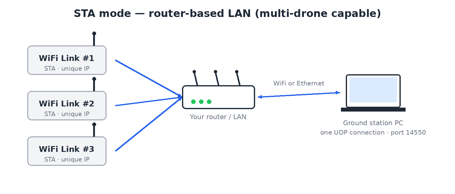
A WiFi radio can play one of two roles. In AP mode (Access Point), the WiFi Link is the network — it broadcasts its own hotspot and your PC or phone joins it, exactly like joining any WiFi network. In STA mode (Station), the module is a client instead: it joins an existing router the same way your phone joins your home WiFi. Nothing about the drone side changes — the flight controller still just talks serial to the module. What changes is where the network lives: on the module itself (AP), or on your router (STA).
Which mode should you use?
| AP mode (default) | STA mode | |
|---|---|---|
| Network setup | None — power on and join the hotspot | Configure each module with AT commands once |
| Range | ~100 m (module ↔ PC/phone direct) | Up to ~500 m through a high-power router |
| Aircraft per ground station | One | Many — this is the multi-drone architecture |
| Ground station connection | Join the module's hotspot | PC joins the router (WiFi or Ethernet) |
| Best for | Bench tuning, single-aircraft field work | Fleets, swarm shows, fixed sites, longer range |
If you just want to tune one aircraft wirelessly, stay in AP mode and skip this tutorial — see the user manual. Come back here when you need more range or more aircraft.
1.2 Parameters to decide before configuring
| Parameter | AT command | Meaning |
|---|---|---|
| Router WiFi name | AT+SSID | The wireless network the WiFi Link should join |
| Router WiFi password | AT+PWD | Password of that network |
| Module local IP | AT+MIP | The WiFi Link's static IP on the LAN |
| Target IP | AT+TIP | The ground-station PC's IPv4 address on the LAN |
| Gateway | AT+GW | The router's gateway IP |
| UDP port | AT+PORT | The port the ground station listens on, usually 14550 |
AT+TIP must be the IPv4 address your ground-station PC actually has on this router — not a made-up address, and not yesterday's address if the router re-assigned it. When telemetry "mysteriously" stops arriving, check this first.
1.3 Find your PC's IPv4 address
- Connect the PC to the router.
- Open the Windows Command Prompt.
- Run:
ipconfig
- Find the IPv4 Address of the active adapter.
Example output:
IPv4 Address . . . . . . . . . . . : 192.168.8.211
Default Gateway  . . . . . . . . . : 192.168.8.1
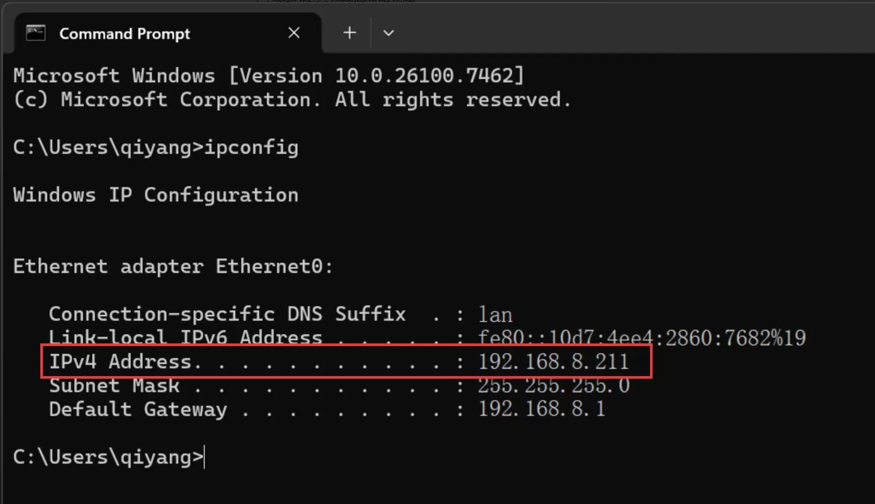
From that output you can plan the addresses:
| Parameter | Example value |
|---|---|
| Ground-station PC IP | 192.168.8.211 |
| WiFi Link module IP | 192.168.8.213 |
| Gateway IP | 192.168.8.1 |
| UDP port | 14550 |
AT+MIP must be in the same subnet as the PC and gateway, and must not collide with any other device on the LAN.
Keep the PC connected to this router from here on. If the PC switches networks or the router hands it a new IP, re-check ipconfig and update AT+TIP on every module.
2. Hardware connections
2.1 While configuring
Configuration only needs the module and a computer:
- Connect the WiFi Link to the PC with a data-capable USB Type-C cable.
- Confirm a new COM port appears in Windows Device Manager.
- No COM port? Install the CH340 driver or swap in a Type-C cable that supports data.
2.2 In use, on the aircraft
Wire the flight controller to the WiFi Link with the supplied cable. This tutorial assumes serial 1, i.e. Telem1:
GH1.25 4-pinend → WiFi LinkSH1.0 4-pinend → flight controllerTelem1
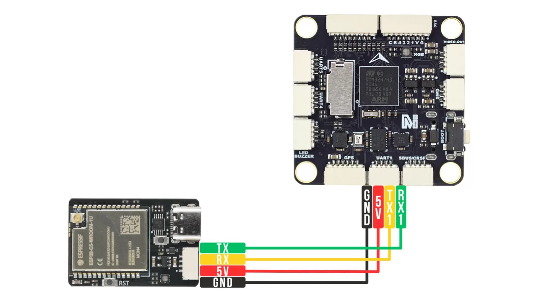
Always configure against the serial port you actually wired — check your flight controller's port mapping.
3. Configure the WiFi Link
3.1 Test AT communication
Any serial terminal works — you don't need a specific program. Four settings matter:
| Setting | Value |
|---|---|
| Port | the WiFi Link's COM port (from Device Manager) |
| Baud rate | 115200 |
| Framing | 8 data bits · 1 stop bit · no parity (8N1, the usual default) |
| Line ending | append CR-LF (\r\n) to every command — the one setting people miss |
Common choices on Windows: PuTTY, Tera Term, or the Arduino IDE Serial Monitor (set the line-ending dropdown to "Both NL & CR" and the baud to 115200). Any of them behaves identically for AT commands.
Open the port and send:
AT
You should get:

No response? Check, in order: correct COM port, baud 115200, CR-LF enabled, data-capable Type-C cable.
3.2 Query the current configuration
AT+ALL?
On a factory-fresh module you'll see the AP-mode defaults:
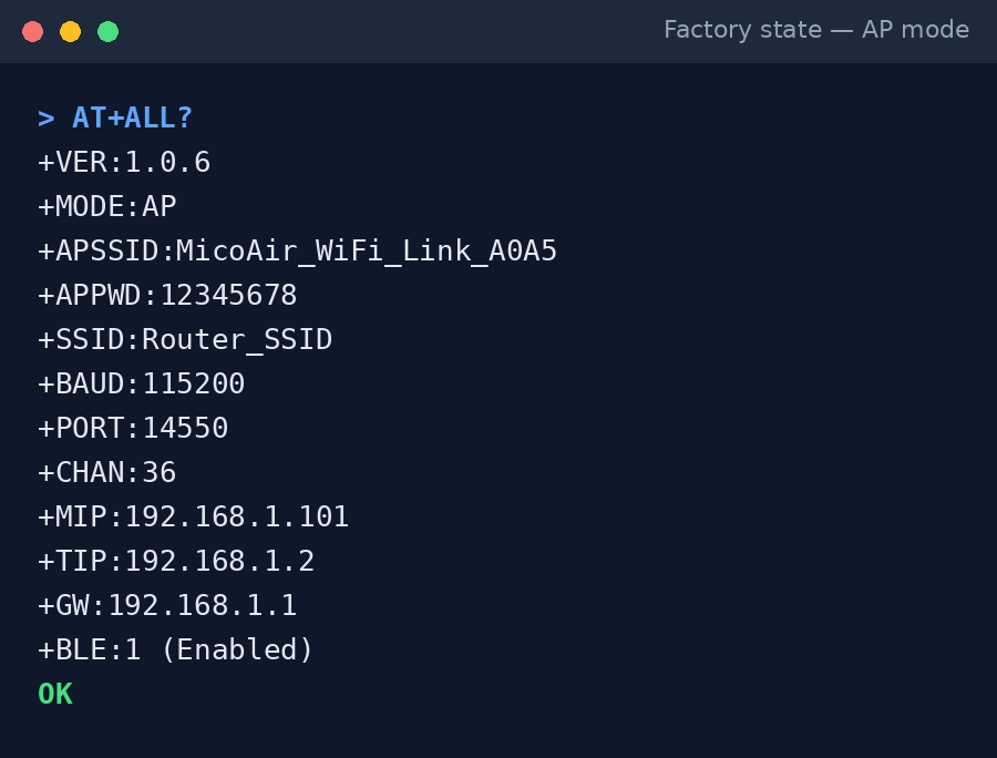
This shows the module's current mode, WiFi name, baud rate, UDP port, local IP and target IP.
3.3 Set the STA network parameters
Switching to STA mode is done over AT commands. (The web page can change some WiFi settings, but this tutorial configures everything through the serial terminal so first-time setups don't mix entry points.)
Example network used below — substitute your real values:
| Parameter | Example value |
|---|---|
| Router WiFi name | MicoAir_5G |
| Router WiFi password | 12345678 |
| Ground-station PC IP | 192.168.8.211 |
| WiFi Link module IP | 192.168.8.213 |
| Gateway IP | 192.168.8.1 |
| UDP port | 14550 |
AT+SSID=MicoAir_5G
AT+PWD=12345678
AT+MIP=192.168.8.213
AT+TIP=192.168.8.211
AT+GW=192.168.8.1
AT+PORT=14550
AT+BAUD=115200
AT+MODE=1
Setting the mode reboots the module automatically. After changing other parameters on their own, reboot manually:
AT+RST
3.4 Verify the configuration took effect
After the reboot, reopen the serial port and send:
AT+ALL?
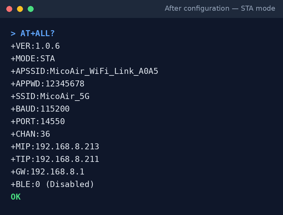
Check each line:
MODEisSTASSIDis your router's WiFi nameBAUDmatches the flight-controller serial baudPORTis the ground-station listening portMIPis this module's own IPTIPis the ground-station PC's IPGWis the router gateway
If the PC later joins another network or gets re-assigned an IP, re-run ipconfig and update AT+TIP.
4. Configure the flight controller
The serial port wired to the WiFi Link must run MAVLink at the same baud rate as AT+BAUD.
4.1 ArduPilot
MicoConfigurator is the recommended tool (download); Mission Planner's full-parameter list works the same way.
- Connect the flight controller to the PC (USB or otherwise).
- Open MicoConfigurator and connect.
- Go to Settings → Ports.
- Find the port the WiFi Link is wired to and set:
SERIAL1_PROTOCOL = MAVLink2
SERIAL1_BAUD = 115200
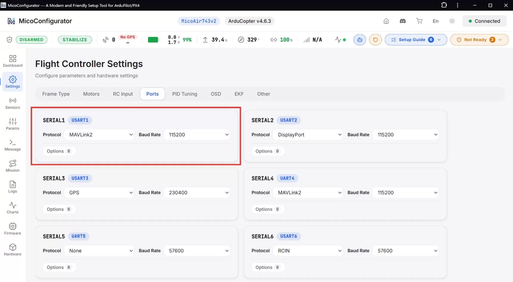
For multiple aircraft, each also needs a unique vehicle number:
- Open Parameters and search
MAV_SYSID(ArduPilot 4.7 and later) orSYSID_THISMAV(4.6 and earlier — the screenshot below shows this older name). - Set it to this aircraft's number.
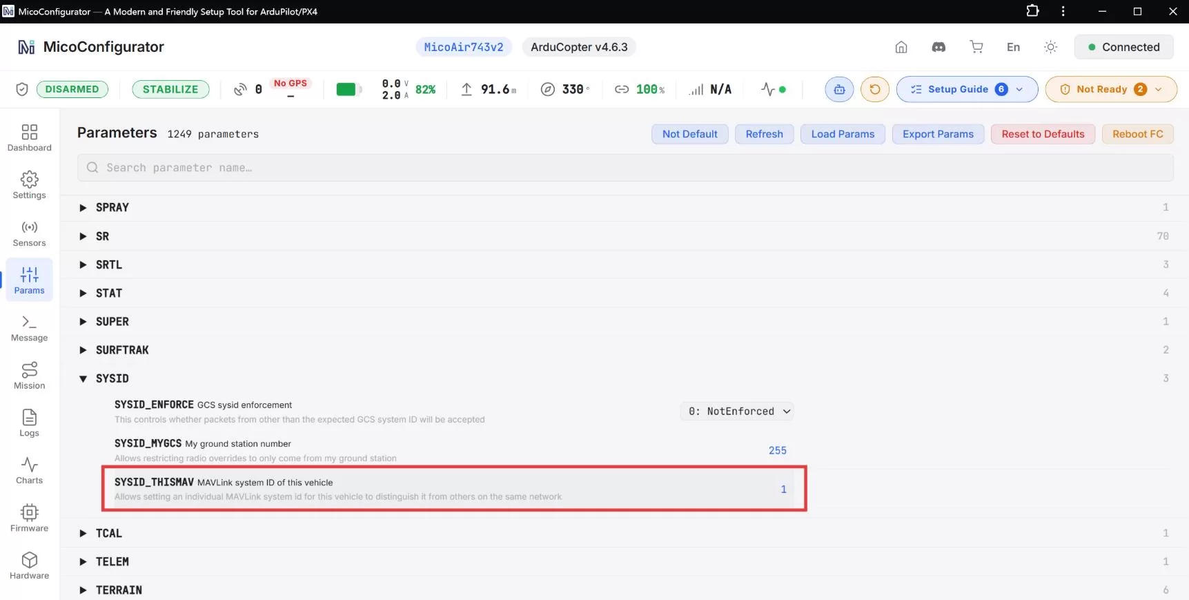
The system ID must be unique per aircraft. For a single aircraft the default 1 is fine. Parameters save automatically; reboot the flight controller to apply.
4.2 PX4
MicoConfigurator is again the recommended tool.
- Connect the flight controller and open MicoConfigurator.
- Go to Settings → Ports.
- With the WiFi Link on
TELEM1, set:
MAV_0_CONFIG = TELEM1
MAV_0_MODE = Normal
SER_TEL1_BAUD = 115200 8N1
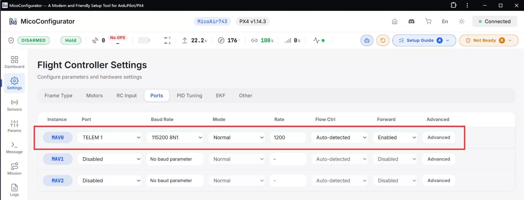
For multiple aircraft, also set a unique:
MAV_SYS_ID
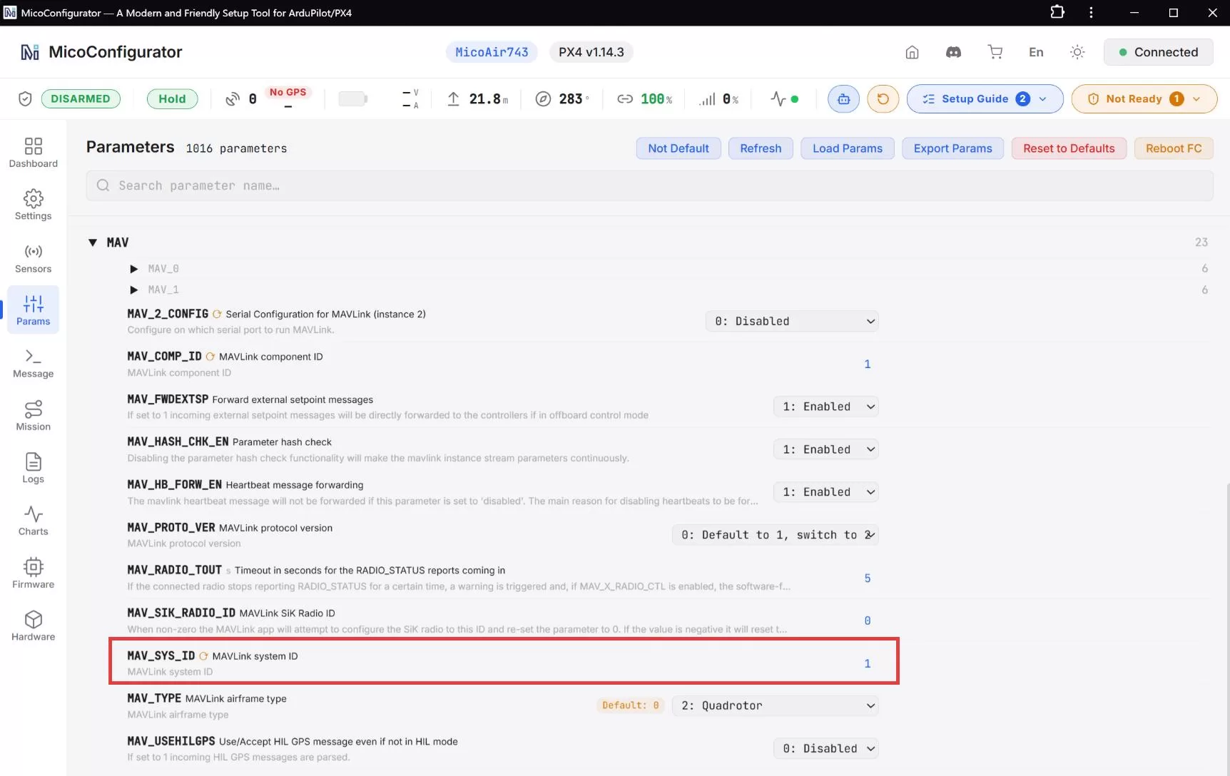
MAV_SYS_ID must be unique per aircraft; default 1 is fine for a single vehicle. Save, then reboot the flight controller.
5. Connect the ground station
With the modules and flight controllers configured, the ground station connects over UDP — and the procedure is identical for one aircraft or many. The GCS listens on one UDP port; every aircraft's data arrives through that single entry point, and the GCS tells them apart by system ID. You connect once, not once per drone.
5.1 Mission Planner
- Open Mission Planner.
- Select UDP as the connection type.
- Set the port to
14550. - Click Connect and wait for the vehicles to appear.

5.2 QGroundControl
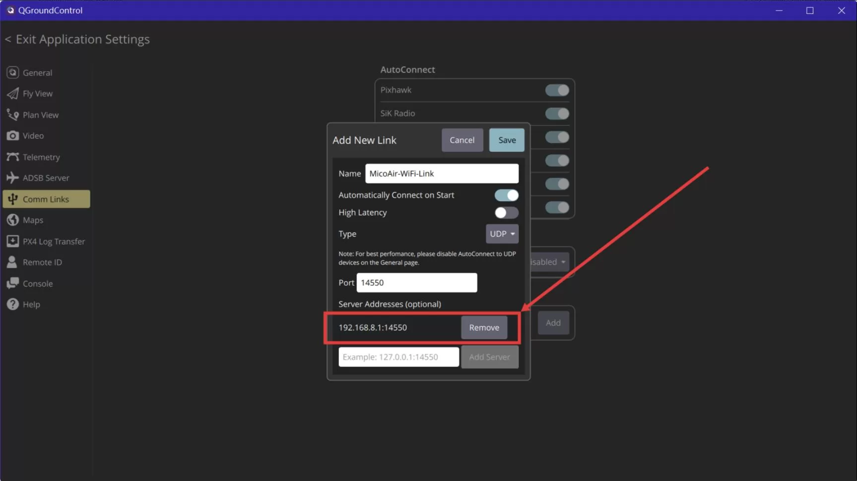
- Open QGroundControl.
- Go to Application Settings → Comm Links.
- Enable UDP auto-connect, or add a manual UDP link.
- Set the listening port to
14550. - Connect and wait for the vehicles to appear.
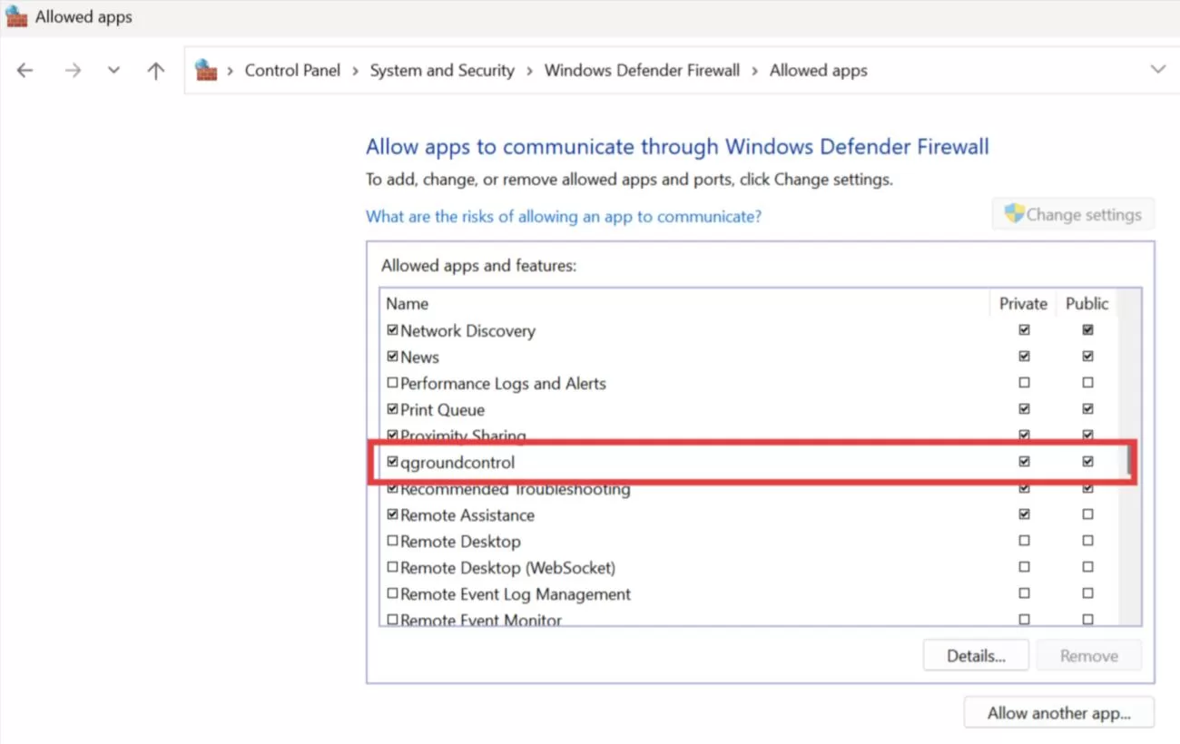
If no data arrives, the first suspect is the Windows Firewall blocking Mission Planner or QGC from receiving UDP.
6. Typical application — controlling a drone swarm
The STA architecture on this page is the communication backbone of most small drone-swarm and light-show setups.
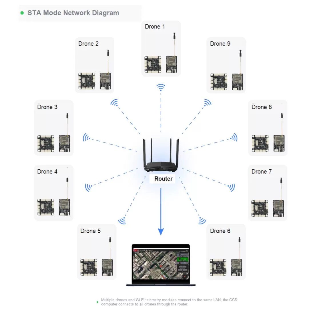
Here's how the pieces map onto a real fleet:
- One LAN carries everything. Every aircraft's WiFi Link joins the same router, and the show computer (ground station) joins it too. There is no per-drone radio pairing — the router is the shared medium, and WiFi 6's OFDMA scheduling is what keeps dozens of small MAVLink streams from trampling each other.
- System IDs are the aircraft's names. The GCS separates vehicles purely by
MAV_SYSID/SYSID_THISMAV(ArduPilot 4.7+ / 4.6) orMAV_SYS_ID(PX4). In a swarm, treat the ID as seriously as the airframe number — most "missing drone" problems trace back to a duplicated ID. - Waypoints and commands upload over the same link. Once the fleet is visible in the GCS, mission upload, parameter changes, arming and mode changes all travel over the LAN — per-aircraft or fleet-wide, depending on your software.
- Swarm software sits on top. Tools like Skybrush (and multi-vehicle setups in Mission Planner/QGC) connect to the very same UDP stream this tutorial configures. If each drone in this tutorial shows up with a unique ID, your platform-level swarm software has everything it needs.
Practical sizing notes from the field:
- Plan the IP block first. Give the GCS a router-reserved static IP, then assign module IPs in a clean sequence (
.212,.213,.214…) that matches airframe numbers — future-you will thank you during a pre-show check. - Prefer 5 GHz for the fleet LAN where your router allows it: more spectrum, less congestion from consumer devices, and it leaves 2.4 GHz cleaner if any aircraft also carry 2.4 GHz RC links.
- Telemetry is light; scale limits come from the router. A MAVLink telemetry stream is a few KB/s per aircraft — a capable WiFi 6 router handles a small show fleet comfortably. Test your full fleet on the ground before the first flight, watching for dropped heartbeats in the GCS.
7. Worked example — three drones, one ground station
Each WiFi Link needs its own local IP, and each flight controller its own system ID. Everything else is shared.
7.1 Network plan
| Device | IP / ID |
|---|---|
| Router gateway | 192.168.8.1 |
| Ground-station PC | 192.168.8.211 |
| Drone 1 WiFi Link | 192.168.8.212 |
| Drone 2 WiFi Link | 192.168.8.213 |
| Drone 3 WiFi Link | 192.168.8.214 |
| UDP port | 14550 |
All three modules point AT+TIP at the same ground-station PC:
AT+TIP=192.168.8.211
…while each module's AT+MIP must be different.
7.2 Per-drone configuration
Drone 1
AT+SSID=MicoAir_5G
AT+PWD=12345678
AT+MIP=192.168.8.212
AT+TIP=192.168.8.211
AT+GW=192.168.8.1
AT+PORT=14550
AT+BAUD=115200
AT+MODE=1
ArduPilot: MAV_SYSID = 1 (SYSID_THISMAV on 4.6) · PX4: MAV_SYS_ID = 1
Drone 2
AT+SSID=MicoAir_5G
AT+PWD=12345678
AT+MIP=192.168.8.213
AT+TIP=192.168.8.211
AT+GW=192.168.8.1
AT+PORT=14550
AT+BAUD=115200
AT+MODE=1
ArduPilot: MAV_SYSID = 2 · PX4: MAV_SYS_ID = 2
Drone 3
AT+SSID=MicoAir_5G
AT+PWD=12345678
AT+MIP=192.168.8.214
AT+TIP=192.168.8.211
AT+GW=192.168.8.1
AT+PORT=14550
AT+BAUD=115200
AT+MODE=1
ArduPilot: MAV_SYSID = 3 · PX4: MAV_SYS_ID = 3
Then connect the ground station exactly as in section 5 — one UDP connection. With unique system IDs, the GCS recognises and lists every aircraft automatically.
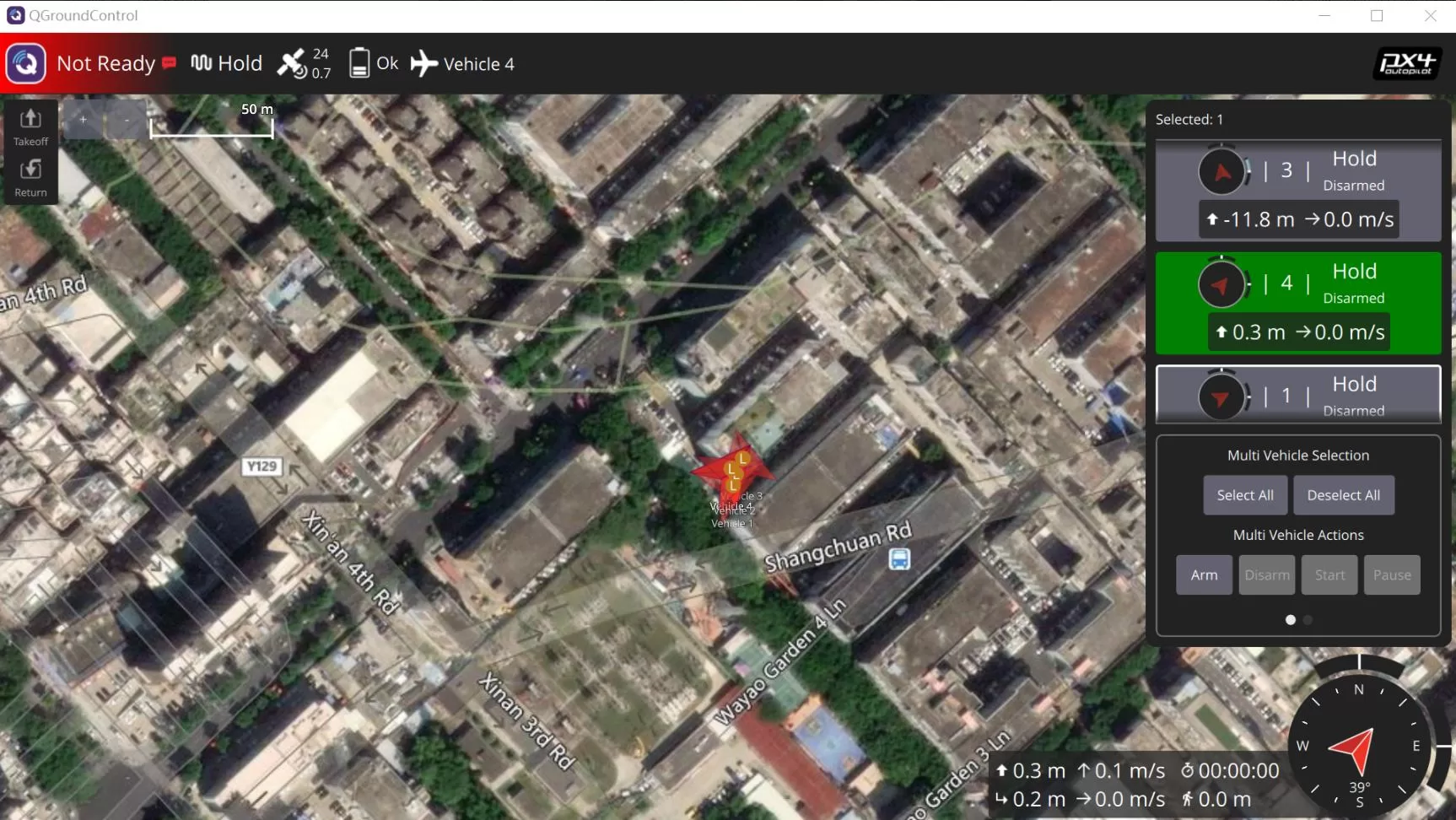
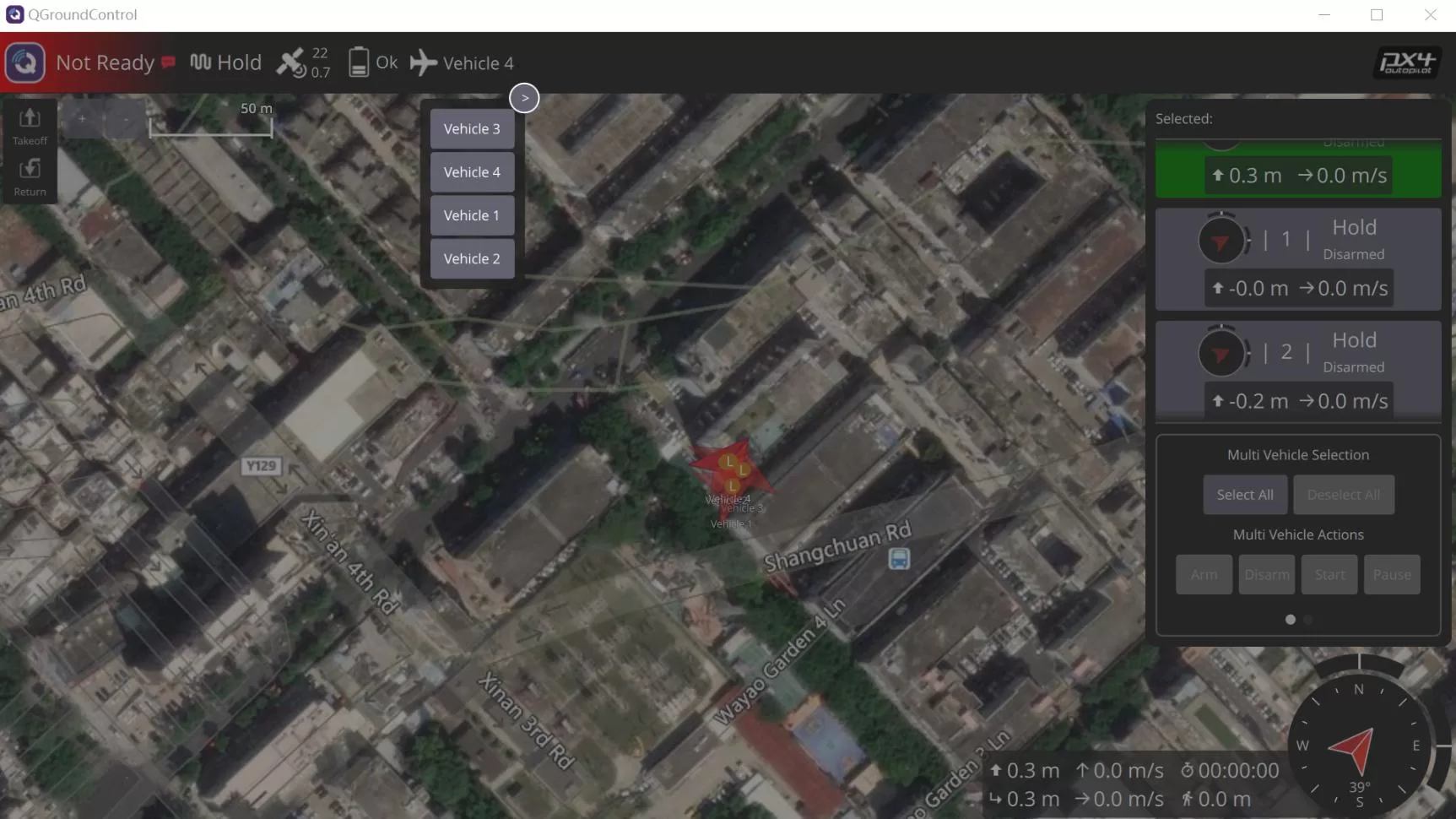
Four-vehicle example under PX4 — QGroundControl lists every vehicle and lets you act on them individually or together:
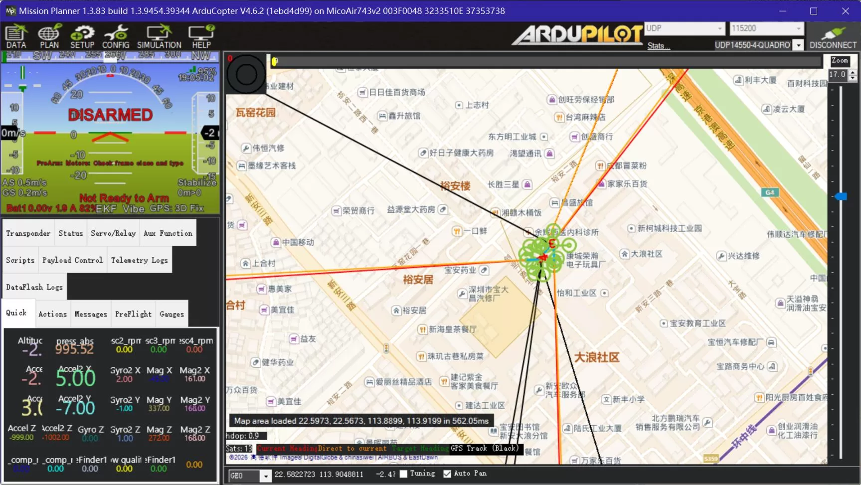
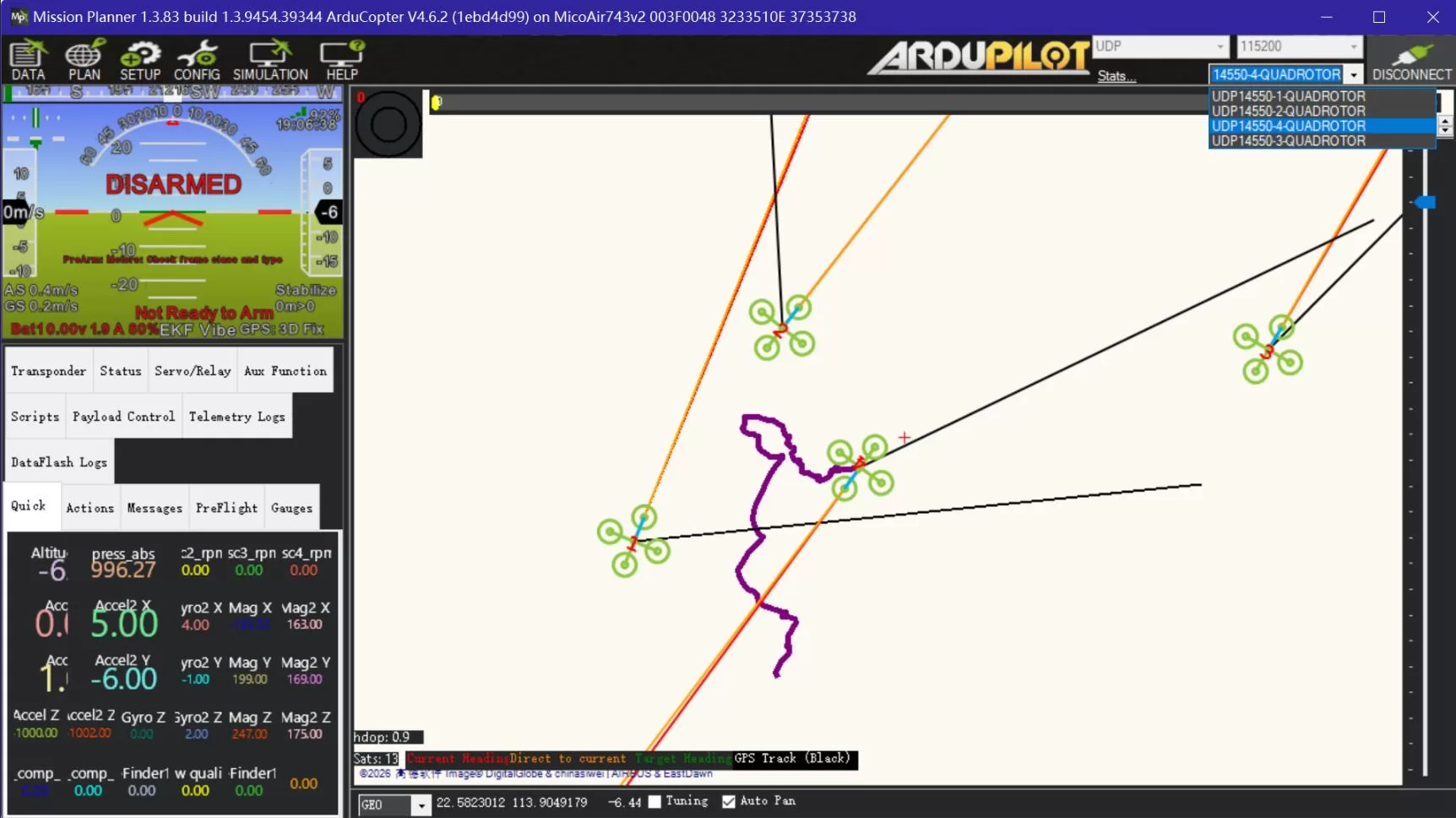
Four-vehicle example under ArduPilot — Mission Planner shows every aircraft on the map and in the vehicle dropdown:
7.3 Multi-drone checklist
- Every module's
AT+MIPis unique. - Every module's
AT+TIPpoints to the ground-station PC. - Every flight controller's system ID is unique.
- If the ground-station PC's IP changes, update
AT+TIPon all modules. - Give the ground-station PC a fixed IP in the router settings — it removes the single most common maintenance chore.
- If some aircraft don't appear after connecting, check for duplicate system IDs first.
8. Troubleshooting
AT commands get no response
- Type-C cable must support data transfer.
- Correct COM port selected.
- Baud rate is
115200. - CR-LF append is enabled.
Module won't join the router
AT+SSIDis correct.AT+PWDis correct.- The router allows new devices to join.
- The module has actually been switched to STA mode.
Ground station receives no data
- The PC's current IP matches
AT+TIP. AT+MIP,AT+TIPandAT+GWare in the same subnet.- The GCS is listening on UDP
14550. - Windows Firewall isn't blocking the GCS.
- The flight-controller serial protocol is set to
MAVLink. - The flight-controller serial baud matches
AT+BAUD. - TX/RX between FC and module are cross-connected.
Parameter changes don't take effect
Reboot the module:
AT+RST
Then confirm with:
AT+ALL?
Start over from a clean state
AT+RESET
restores factory defaults; then reconfigure STA mode from section 3.
Get the hardware
The MicoAir WiFi Link is available from Robofusion: robofusion.net
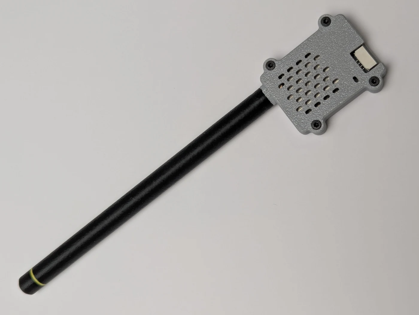
Robofusion has designed a free 3D-printable case and antenna radome for the WiFi Link (the module ships as a bare board) — shown above as printed. Both downloads include the model files and print profiles:
- Download on MakerWorld — print straight from the MakerWorld profile.
- Direct download (ZIP) — all model and print-configuration files in one package.
Related guides
Where to buy
One module per aircraft, shipped from Canada with free Canada-wide shipping:
- MicoAir WiFi Link — dual-band WiFi 6 telemetry module
Written and maintained by the Robofusion engineering team.