MicoAir TRS — 2.4 GHz RC + Telemetry Combo User Manual
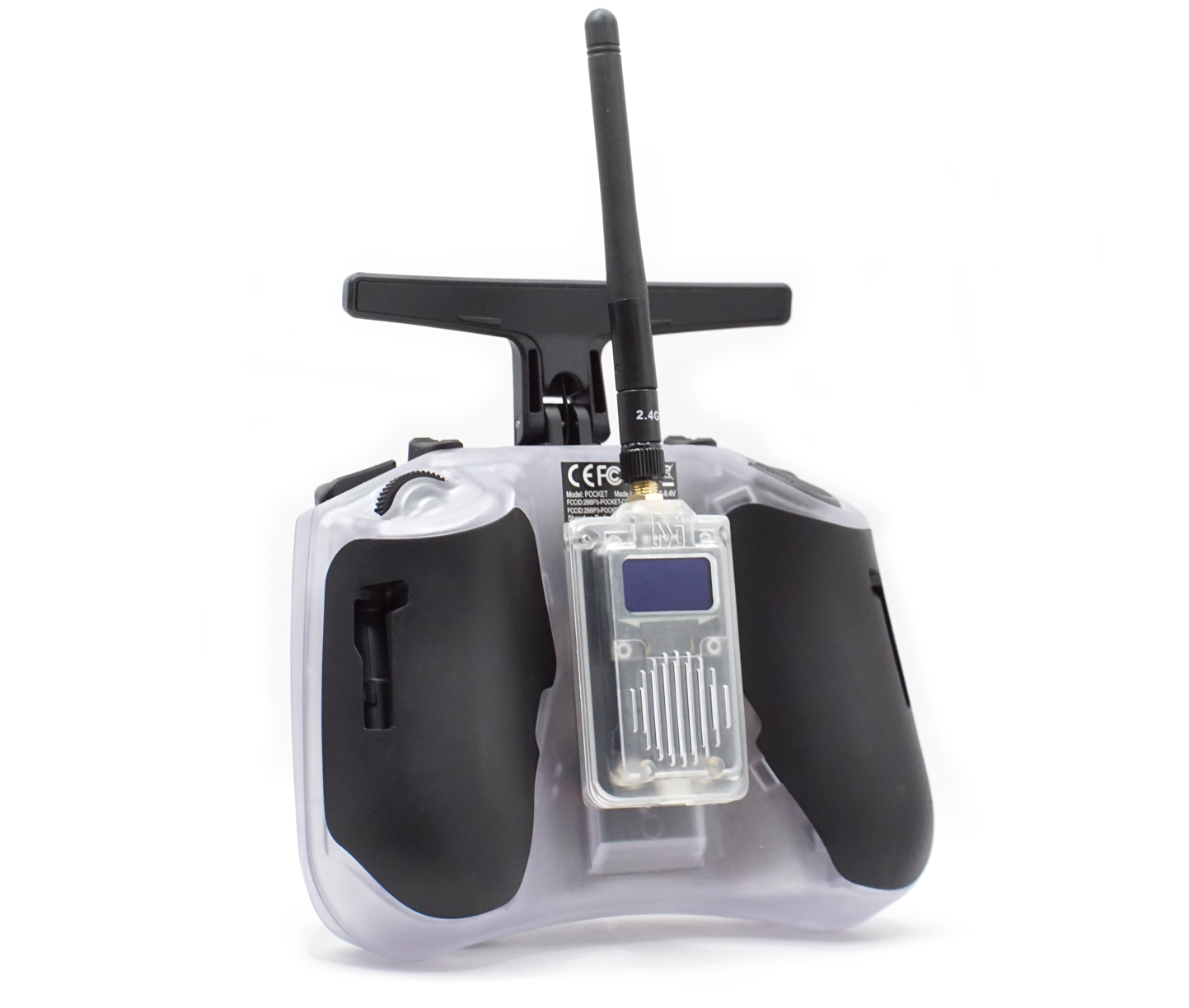
The TRS is an integrated radio-control + telemetry communication system on a single 2.4 GHz link. It has two parts: a TX module that slots into your radio controller, and a tiny receiver on the aircraft that outputs SBUS for control and a serial telemetry port for MAVLink. One encrypted LoRa/FHSS link carries your stick inputs and your Mission Planner/QGC data — at the same time, in both directions.
Where to buy
- Robofusion store (ships from Canada — free Canada-wide shipping): TRS 2.4GHz RC + Telemetry 2-in-1 System
New to this? Why "RC + telemetry in one" matters
A conventional long-range build carries two independent radio links: an RC system (say, ELRS) for control, and a separate telemetry radio (like the LR900 or LR24) for ground-station data. That's two receivers to mount, two antennas to place, two frequency plans to keep from fighting each other.
The TRS folds both jobs into one link:
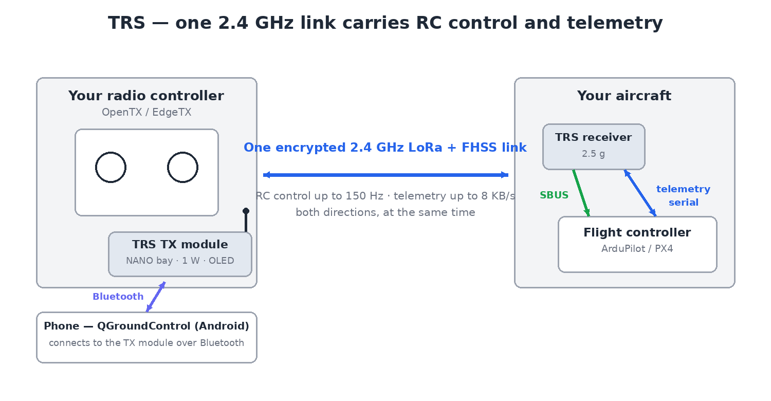
- The TX module rides in your radio's external module bay and talks to the aircraft.
- The receiver outputs SBUS (the RC protocol virtually every flight controller accepts) to the FC's RC-in, and a telemetry serial stream to a TELEM port.
- Your ground station connects through the TX module — including wirelessly from a phone over built-in Bluetooth.
One link also means no 2.4 GHz self-interference problem — the usual warning against putting a 2.4 GHz RC receiver next to a 2.4 GHz telemetry radio doesn't apply, because control and telemetry share the same coordinated FHSS transmission.
Key specifications
Link
| Item | Specification |
|---|---|
| Band | 2.4 GHz |
| Technology | LoRa spread spectrum + encrypted FHSS hopping |
| TX module power | up to 27 dBm (500 mW) |
| Receiver power | up to 27 dBm (500 mW), self-adaptive |
| Range | 10–15 km effective in open, interference-free conditions (farther with a high-gain directional antenna on the TX module); 3–5 km with light interference, unobstructed |
| Telemetry throughput | up to 8 KB/s bidirectional |
| RC update rate | up to 150 Hz |
| RC output protocol | SBUS |
Compatibility
- TX module bay: NANO — fits compact OpenTX/EdgeTX radios (Radiomaster Pocket, Jumper T-Pro, etc.); traditional JR-bay radios via a JR→NANO adapter.
- Flight controllers: anything that speaks SBUS + MAVLink serial telemetry — ArduPilot and PX4 included.
- Ground stations: Mission Planner / QGC on the bench via the TX module; QGroundControl on Android over Bluetooth wirelessly.
Physical
| TX module | Receiver | |
|---|---|---|
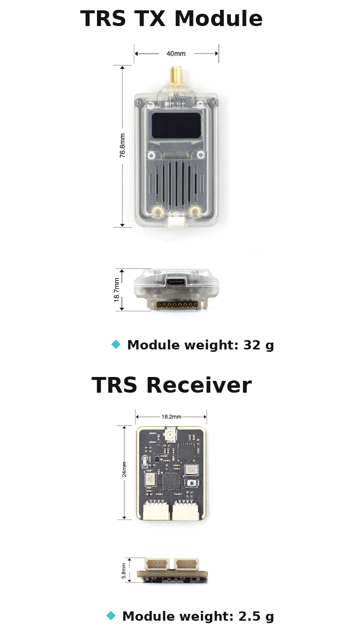
| Dimensions | 76.8 × 40 × 18.7 mm | 24 × 18.2 × 5.8 mm |
| Weight | 32 g | 2.5 g |
Work modes — range vs. responsiveness
The TRS trades range against control rate and data rate in three fixed modes:
| Mode | long-range | standard | high-speed |
|---|---|---|---|
| Telemetry rate | 2.4 KB/s | 4 KB/s | 8 KB/s |
| RC update rate | 50 Hz | 100 Hz | 150 Hz |
| Serial baud rate | 57600 | 57600 | 115200 |
| Relative range | ★★★ | ★★ | ★ |
How to choose:
- Long-range — maximum reach; 50 Hz control is plenty for cruising wings, mappers and anything that isn't acro.
- High-speed — snappiest stick feel and the fastest parameter/mission transfers, at reduced range.
- Standard — the middle path.
Two things the system handles for you:
- The TX module's baud rate is tied to the mode — you never set it manually.
- The receiver adopts the matching telemetry baud automatically after re-binding. Example: switch the TX module to high-speed, re-bind, and the receiver's serial port is now 115200 — remember to set the flight-controller port to match (57600 in long-range/standard, 115200 in high-speed).
Binding
The receiver LED tells you everything: solid = linked, slow blink = not connected, fast blink = binding mode.
- Hold the receiver's bind button and power it on — the LED blinks rapidly (binding mode).
- Power on (or power-cycle) the radio with the TX module installed — the pair binds automatically within a few seconds; the receiver LED goes solid.
TX module OLED
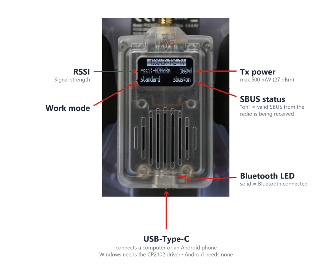
The TX module's OLED shows the link's working state at a glance — mode, power, and connection status:
Receiver wiring
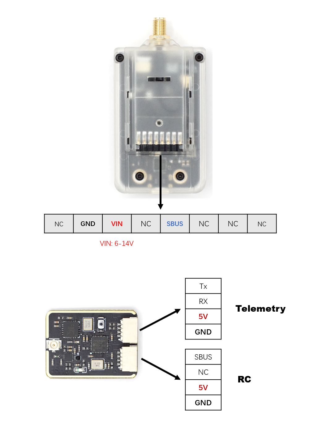
- SBUS out → the flight controller's RC input.
- Telemetry serial → a flight-controller TELEM/serial port — same three rules as any telemetry radio: TX↔RX crossed, common ground, matching baud rate.
- Configure the FC's serial port for MAVLink as in the ArduPilot / PX4 telemetry guides, with the baud from the mode table above.
Configuration and driver
TX-module parameters are configured with MicoAssistant over USB — select the baud rate matching the module's current mode.
- Windows needs the CP2102 driver first: CP2102 Driver Installation (Windows).
- Android needs no driver.
Connect QGroundControl on Android over Bluetooth
The TX module's built-in Bluetooth lets an Android phone running QGC become your wireless ground station — no cable to the radio.
-
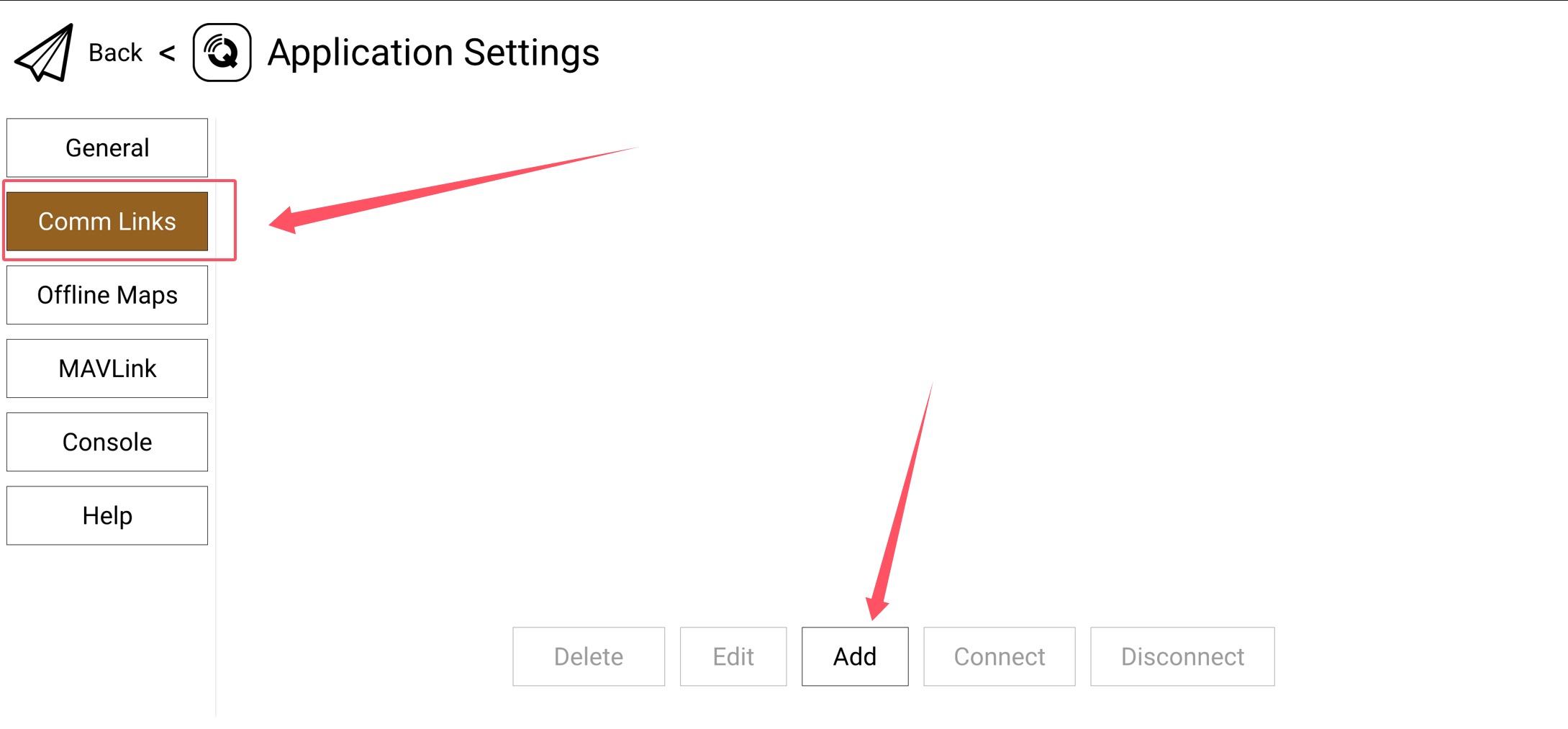
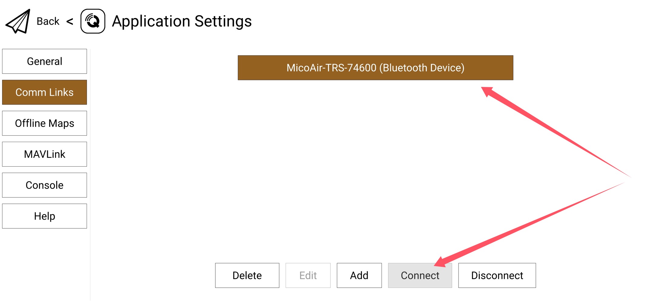
Open the QGC app → Application Settings → Comm Links → Add.
-
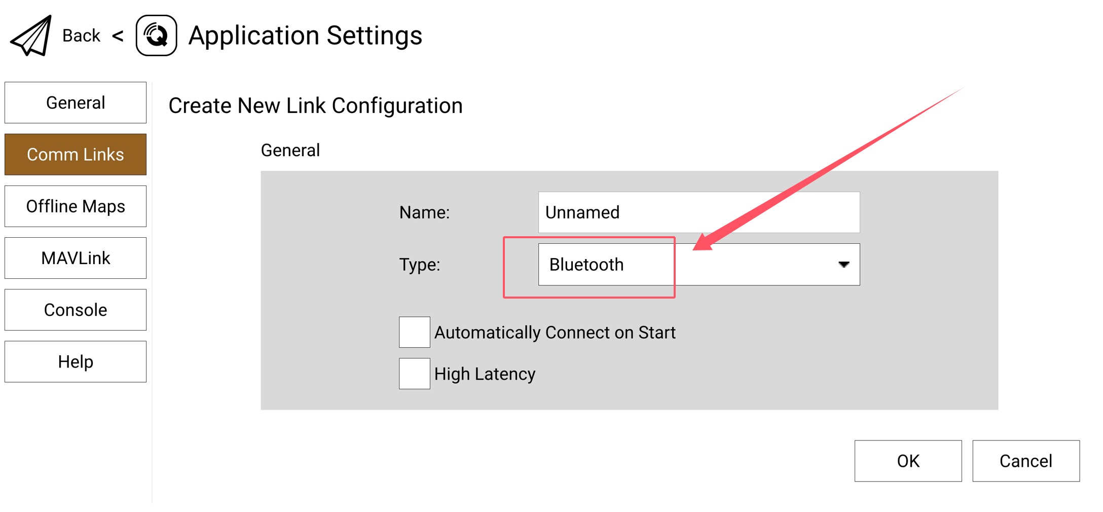
Set the connection Type to Bluetooth.
-
Scroll down, tap Scan with the phone near the radio — the TX module appears as
MicoAir-TRS-xxxxx. Select it and tap OK.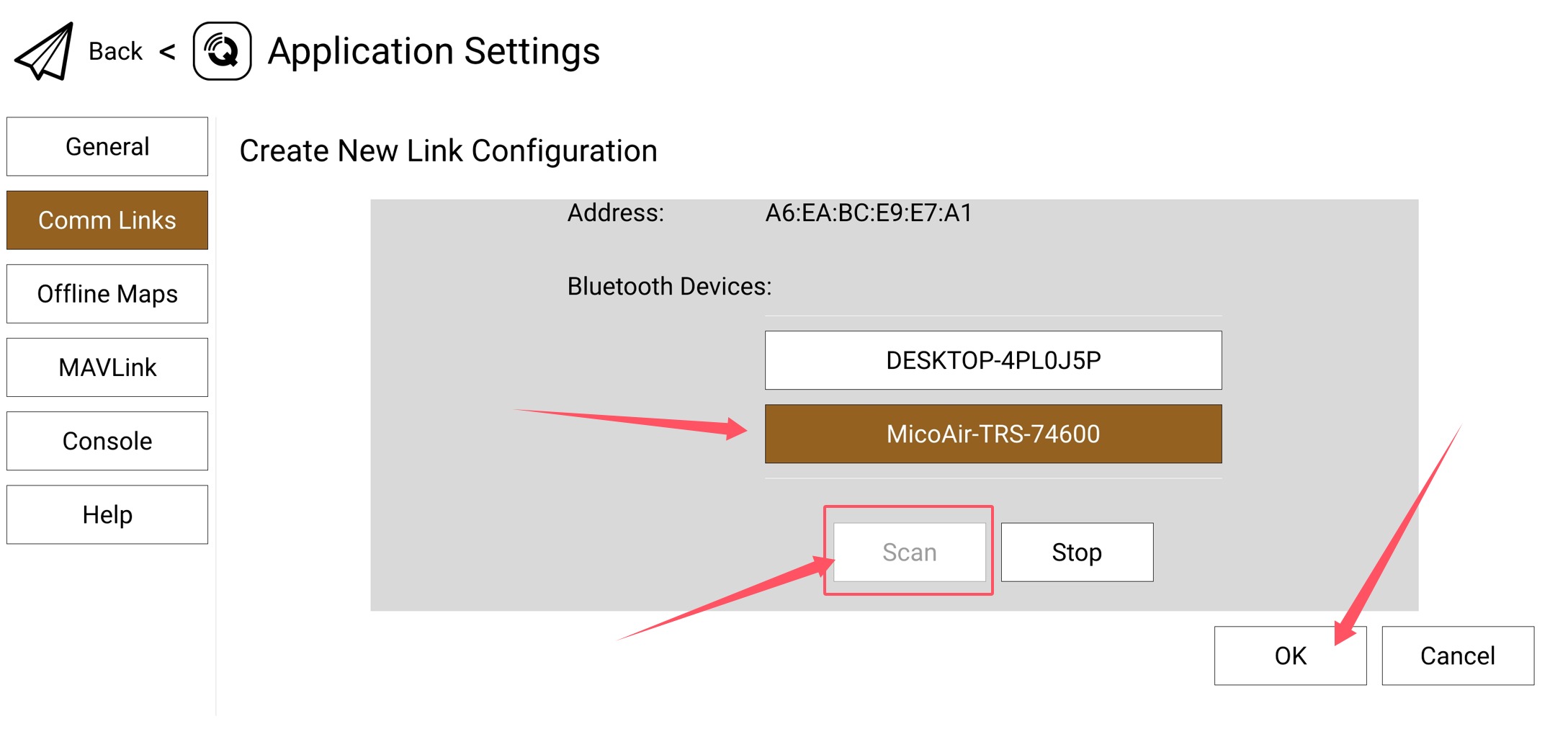
-
Back in Comm Links, select the new Bluetooth link and tap Connect. After a few seconds the TX module's Bluetooth indicator turns solid.
-
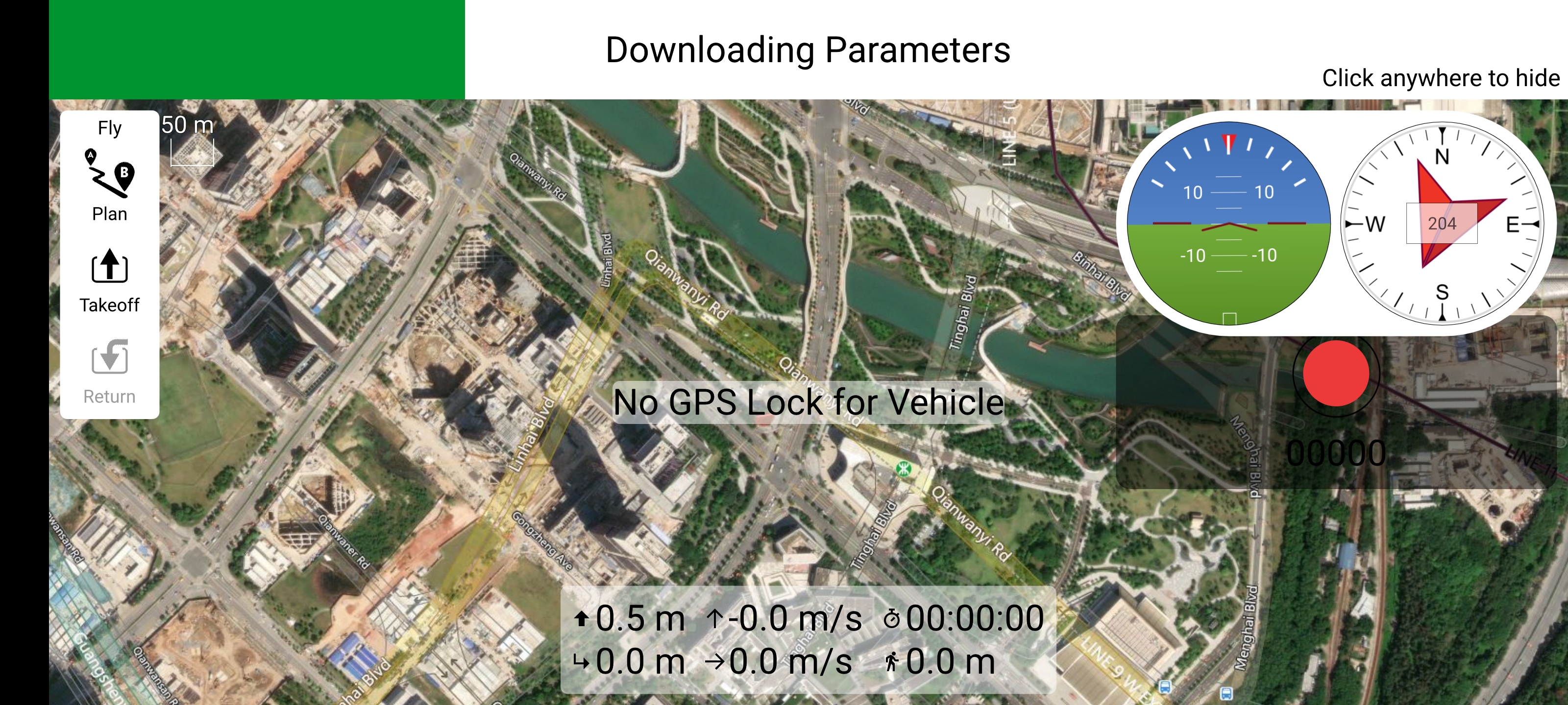
Return to the QGC main view — the app connects to the flight controller and loads its parameters (provided the TX module and receiver are bound, and the receiver's telemetry port is wired and configured on the FC).
How do I show link RSSI in my ground station?
RSSI — received signal strength indicator — is the number that tells you how much link margin you have left before the control link starts dropping frames. It is the single most useful thing to have on the HUD when you fly far.
On most RC systems, getting RSSI to the flight controller means an extra signal wire from the receiver to an analogue or PWM input. The TRS receiver doesn't need one: it writes RSSI into channel 12 of its own SBUS output, so the value arrives on the wire that is already there. All you do is tell the flight controller to look at that channel.

ArduPilot — connect the flight controller in MicoConfigurator and open Settings → RC Input. Set the RSSI source to RCChannelPwmValue (meaning: read RSSI from an RC channel rather than from a pin) and set the channel to CH12. In a full parameter list those are RSSI_TYPE = 2 and RSSI_CHANNEL = 12. Values save as you change them; if RSSI still reads zero afterwards, reboot the flight controller.
PX4 — open Params, search for RC_RSSI_PWM_CHAN and set it to Channel 12. The value is stored straight away, but PX4 only starts using the new channel after a reboot.
With that done the flight controller passes RSSI up the telemetry stream like any other sensor value, so it shows on the HUD in Mission Planner or QGroundControl without any further setup.
Once the receiver is writing RSSI into channel 12, don't also map a switch, a gimbal axis or a servo to channel 12 on the radio — the flight controller would read that as a signal-strength reading. Use channels 1–11 and 13–16 for controls.
FAQ
Which radios does the TX module fit?
Compact OpenTX/EdgeTX radios with a NANO module bay (Radiomaster Pocket, Jumper T-Pro and similar) directly; JR-bay radios via a JR→NANO adapter.
Do I still need an LR900 or LR24 with this?
No — telemetry is built into the link. Choose the TRS when you want one radio system for both jobs; choose a dedicated telemetry radio when your RC link is already decided or the ground side isn't a hand-held radio (e.g. RTK, fixed ground stations).
The receiver LED blinks slowly and won't connect
Slow blink = not linked. Re-bind (button + power on the receiver, then power-cycle the radio), check both ends are powered, and check the TX module is seated in the bay.
No telemetry in the ground station, but RC works
RC and telemetry share the link, so if sticks work the RF side is fine — the issue is on the wire: check the receiver's telemetry serial is wired crossed to the FC port, the FC port is set to MAVLink at the mode's baud rate (57600 or 115200), and you re-bound after any mode change so the receiver's baud followed.
RSSI shows zero in the ground station
The flight controller has not been told where to find it. Set RSSI_TYPE = 2 and RSSI_CHANNEL = 12 on ArduPilot, or RC_RSSI_PWM_CHAN = 12 on PX4, then reboot the flight controller — see the RSSI section above.
Can iOS QGC connect over Bluetooth?
Bluetooth GCS connection is currently supported with QGroundControl on Android.
Related guides
- LR24 2.4 GHz Telemetry Radio — User Manual
- LR900 Telemetry Radio — User Manual
- ArduPilot — Telemetry Setup Guide
- PX4 — Telemetry Setup Guide
- CP2102 Driver Installation (Windows)
Written and maintained by the Robofusion engineering team.