MicoVIO Visual-Inertial Odometry Sensor — User Manual
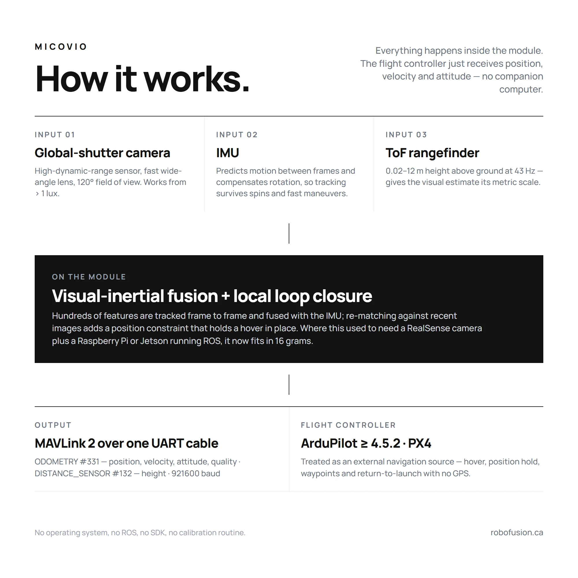
The MicoVIO is MicoAir's visual-inertial odometry (VIO) module: a global-shutter camera, an IMU and a ToF rangefinder in a 29.5 × 29.5 × 15 mm aluminium case, with all the fusion done on board. It outputs the aircraft's relative position, 3-axis velocity and attitude as standard MAVLink 2 ODOMETRY messages, so an ArduPilot or PX4 drone can hover, hold position, fly waypoints and return to launch without GPS — indoors, under bridges, in tunnels and warehouses, or anywhere satellites fail. Typical trajectory error is 1 % of distance flown. It weighs 16 g and needs nothing but a spare UART.
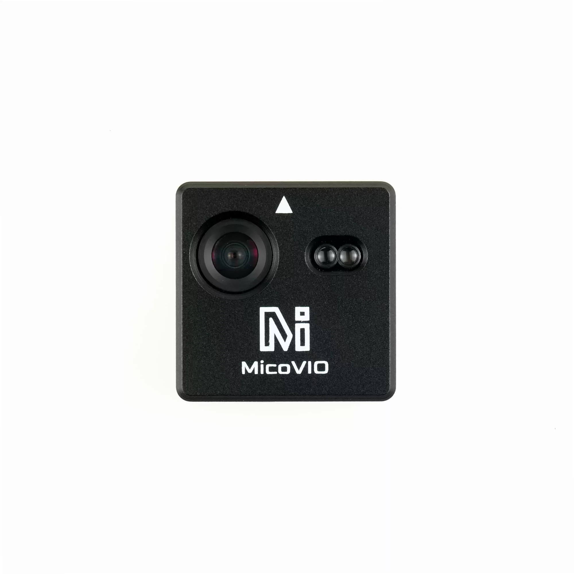
MicoVIO launched in China on 15 October 2026 and the first North American stock is on its way to Robofusion. The store page is live for reference, and the cart stays closed until units arrive. To reserve one, email info@robofusion.net with the quantity — nothing is charged until we ship.
Where to buy
- Robofusion store (ships from Canada — free Canada-wide shipping): MicoAir MicoVIO — pre-orders by email until the first batch lands.
- Not sure whether you need VIO or optical flow? Read VIO vs Optical Flow — what's the difference? first.
What VIO is — and why it is not "better optical flow"
An optical flow sensor watches the ground slide across a tiny camera and tells the flight controller how fast the aircraft is moving sideways. The EKF integrates that velocity to get a position, and because every small error is integrated too, the position drifts. Flow quality also collapses when the aircraft yaws quickly or climbs too high.
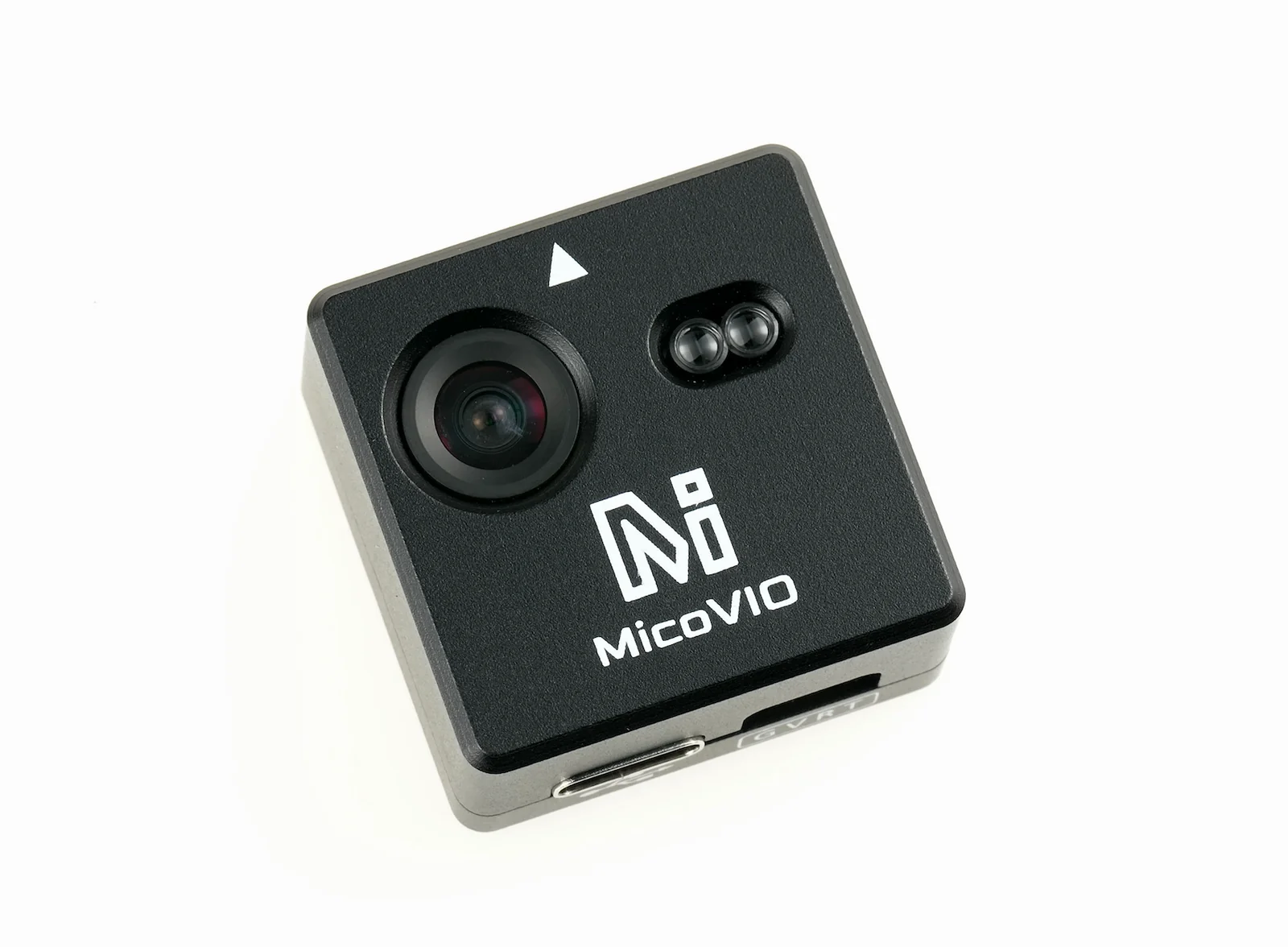
Visual-inertial odometry solves a different problem. It tracks hundreds of visual features from frame to frame, predicts the motion between frames with the IMU, and fuses the two into a full 6-degree-of-freedom pose — where the aircraft is, how fast it moves, and which way it points. The ToF rangefinder pins down the metric scale. The result is a position the autopilot can trust, not just a velocity. MicoVIO adds local loop closure: it re-matches the current view against recent frames and uses that as a position constraint, so a hover stays put instead of slowly wandering.
Open-source VIO pipelines normally run on a Linux board (Jetson, Raspberry Pi, VOXL) with a stereo camera and ROS, and they are notorious for diverging when the light changes or the aircraft is bumped. MicoVIO runs the whole pipeline on the module and holds through strong light changes, impacts and fast attitude changes — which is what makes a 16-gram, plug-into-a-UART VIO sensor possible at all.
Standalone: the whole VIO pipeline in 16 grams — no companion computer
This is the point that matters most. Until now, giving an open-source drone visual-inertial odometry meant building a small computer onto it: a stereo or tracking camera such as the Intel RealSense D435 or T265, a Raspberry Pi, Jetson or similar single-board computer to run the VIO software under ROS, a power supply for it, and a MAVLink bridge back to the flight controller. That stack costs several hundred dollars, weighs well over a hundred grams with its cabling, needs a frame big enough to carry it, and takes days to integrate — and the open-source VIO it runs is known for diverging when the light changes or the aircraft is bumped.
MicoVIO puts the camera, the IMU, the rangefinder and the fusion processor inside one 29.5 × 29.5 × 15 mm, 16 g module and talks to the flight controller the way a GPS does: one 4-pin UART cable, standard MAVLink 2. There is no operating system to install, no ROS, no SDK, no calibration routine and nothing else to power. A 3-inch quad can carry it. For the flight controller it is simply an external navigation source — the same VISO_TYPE / EKF2_EV_CTRL settings used for a motion-capture system or a VOXL — so an ArduPilot or PX4 aircraft that has never had GPS-free positioning gets it in an afternoon.
| Traditional VIO stack | MicoVIO | |
|---|---|---|
| Hardware | Stereo / tracking camera (D435, T265) + Raspberry Pi / Jetson + power + cabling | One module |
| Weight | Well over 100 g all-in | 16 g |
| Cost | Several hundred dollars | A fraction of that |
| Software | ROS, VIO package, MAVLink bridge, calibration | None — MAVLink 2 out of the box |
| Interface to FC | MAVLink over serial or Ethernet from the companion computer | 4-pin UART, 921600 baud |
| Robustness | Open-source VIO often diverges under light changes or impacts | Holds through strong light changes, impacts and fast attitude changes |
| Minimum airframe | Typically 5-inch and up | 3-inch and up |
Specifications
Positioning & tracking
| Item | Specification |
|---|---|
| Method | Visual-inertial fusion of camera + IMU, with ToF rangefinder for height and scale |
| Output | Relative position, 3-axis velocity, attitude, height above ground, positioning quality |
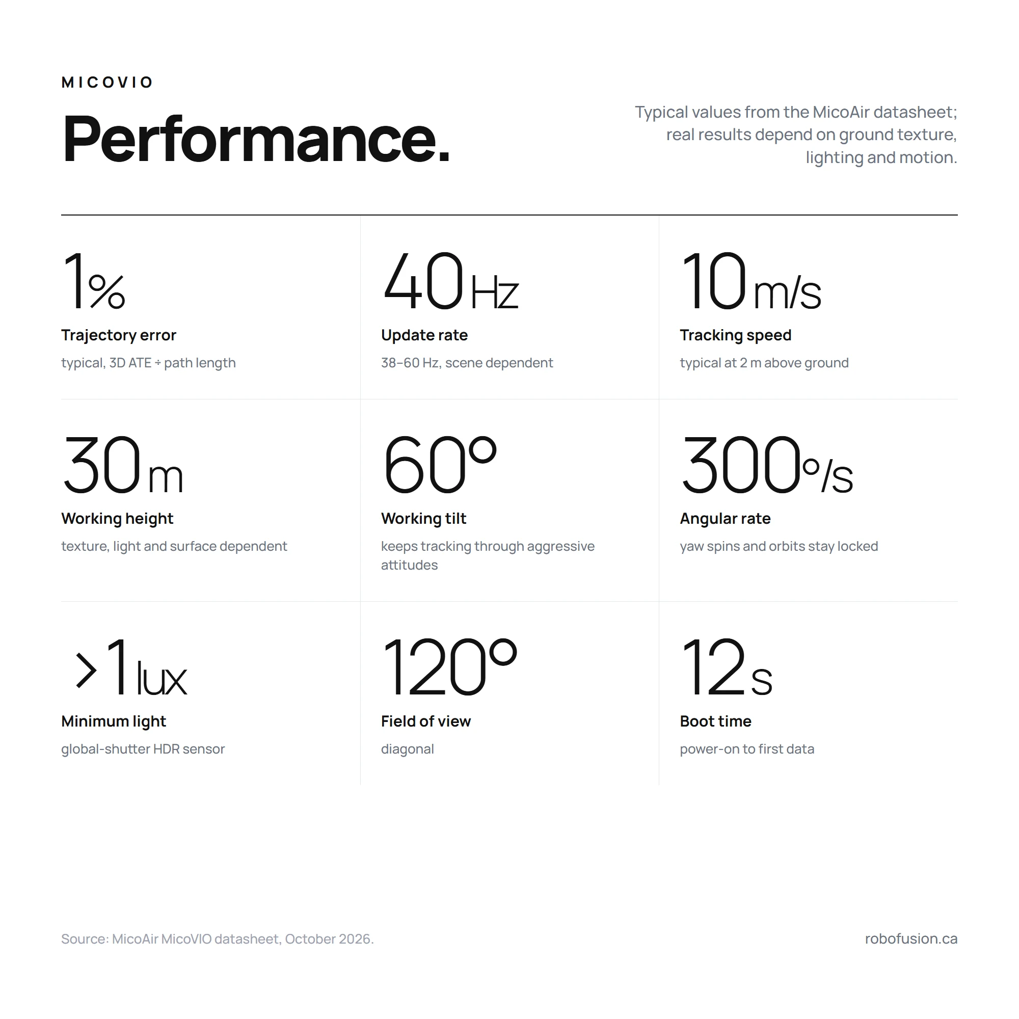
| Trajectory error | 1 % typical¹ |
| VIO update rate | 40 Hz typical (38–60 Hz, varies with scene texture) |
| Tracking speed | 10 m/s typical at 2 m above ground; varies with height, light, texture and motion |
| Max VIO working height | 30 m; effective height depends on ground texture, lighting and reflectivity |
| Min. initialisation height | 1 cm² |
| Max working tilt | 60° |
| Max tracking angular rate | 300°/s |
| Local loop closure | On by default; improves hover accuracy, does not affect dynamic flight |
| Boot time | ≈ 12 s from power-on to first data |
Vision & ranging
| Item | Specification |
|---|---|
| Image sensor | Large-format, high-dynamic-range global-shutter sensor with a fast wide-angle lens |
| Lens FOV | 120° diagonal |
| Illumination | > 1 lux |
| ToF range | 0.02–12 m — 12 m indoors or under overcast sky, about 8 m in bright sunlight³ |
| ToF update rate | 43 Hz |
Interface & protocol
| Item | Specification |
|---|---|
| Protocol | MAVLink 2 |
| Odometry message | ODOMETRY (ID 331) |
| Range message | DISTANCE_SENSOR (ID 132) |
| Serial | 3.3 V LVTTL UART, 921600 baud, 8N1 |
| Connectors | GH1.25-4P (GND · VCC · RX · TX) to the flight controller · USB Type-C for setup |
| Firmware | ArduPilot ≥ 4.5.2 · PX4 |
Electrical & mechanical
| Item | Specification |
|---|---|
| Supply | 5 V |
| Current / power | ≈ 200 mA average · ≈ 1 W |
| Size | 29.5 × 29.5 × 15 mm |
| Weight | 16 g |
| Mounting | Facing down, white arrow toward the nose |
¹ Typical 3D absolute trajectory error (ATE RMSE) divided by reference path length; varies with environment and motion. ² The height from which initialisation is allowed — not a guarantee of ToF or positioning accuracy at that height. ³ Ranging is affected by ambient light, target reflectivity, incidence angle and mounting.
Measured: outdoor trajectory vs RTK
MicoAir flew the module outdoors next to an RTK receiver and compared the two tracks. ATE is the RMS 3D distance between the MicoVIO trajectory and the RTK trajectory after rigid-body alignment, with no scale correction.
| Flight | Horizontal distance travelled | ATE | ATE as share of distance |
|---|---|---|---|
| 1 | ≈ 136 m | 0.73 m | ≈ 0.5 % |
| 2 | ≈ 141 m | 0.70 m | ≈ 0.5 % |
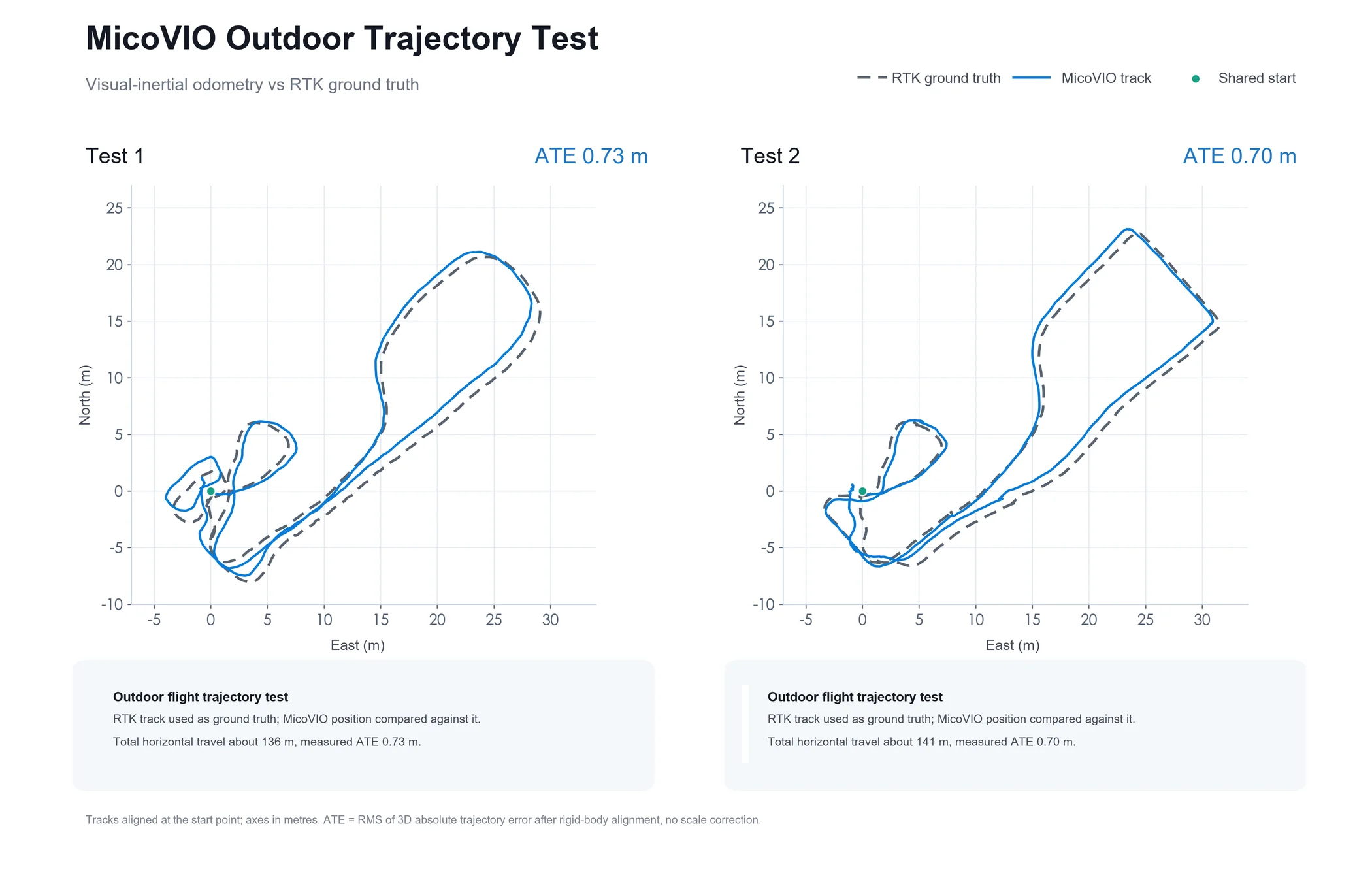
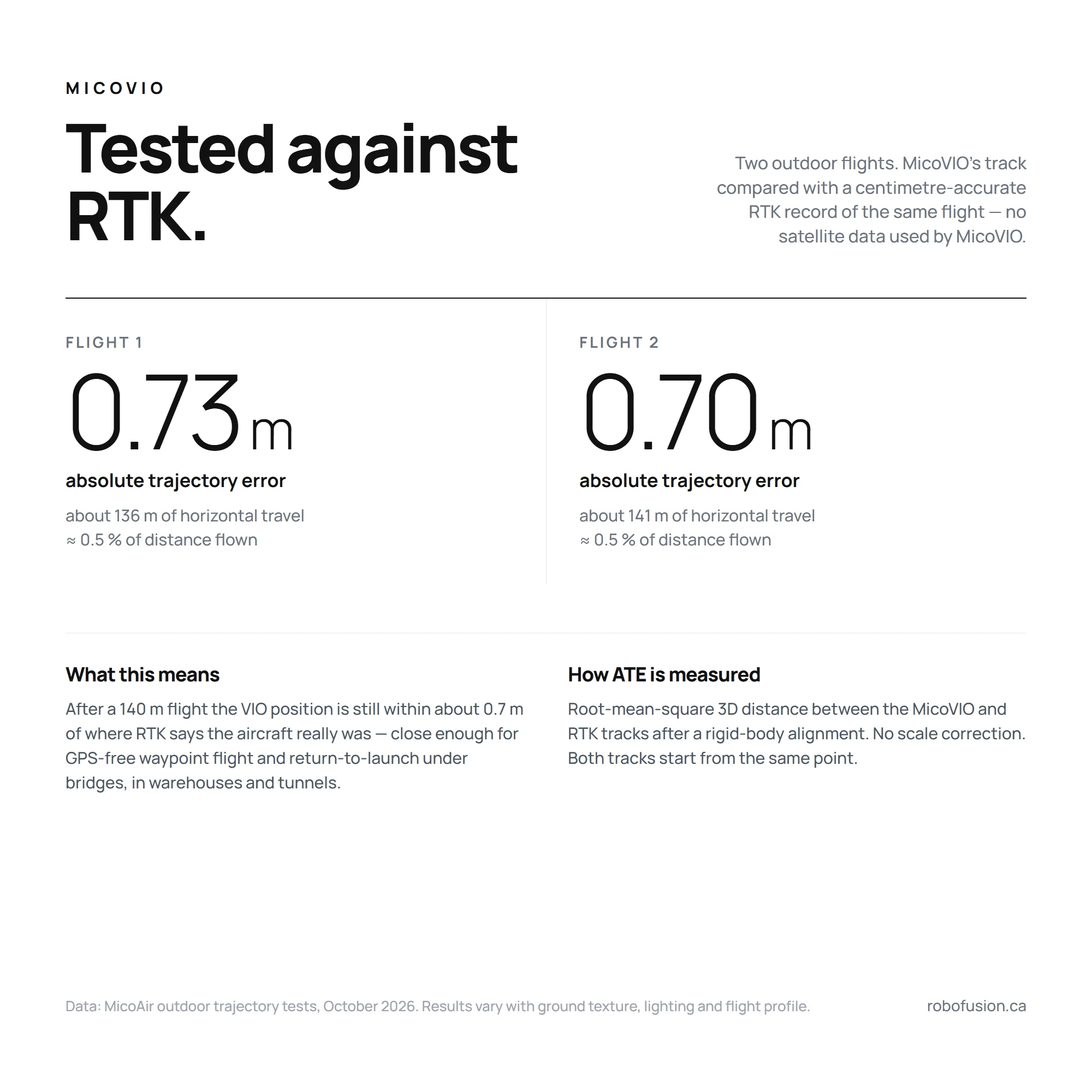
In practice: after a 140 m flight with no satellite data, the VIO position is still within about 0.7 m of where a centimetre-grade RTK receiver says the aircraft really was. That is what makes GPS-free waypoint flight and return-to-launch realistic (RTL requires firmware support for external-navigation RTL).
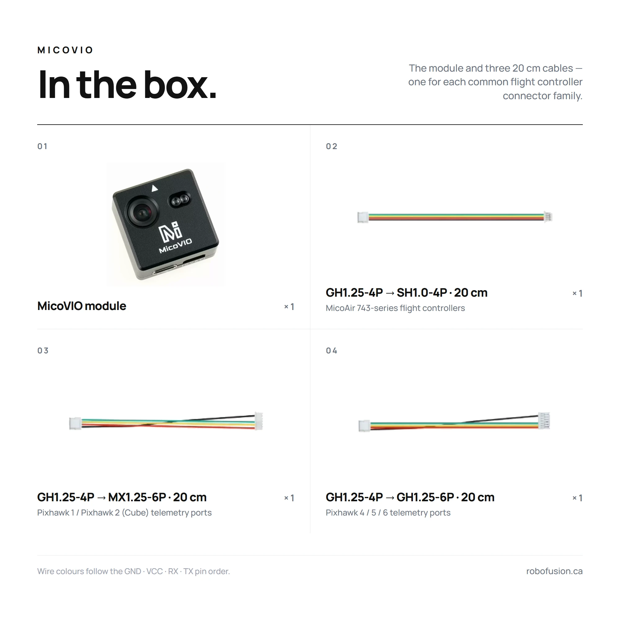
What's in the box
| Item | Qty | Fits | |
|---|---|---|---|
| MicoVIO module | 1 | — | |
| GH1.25-4P → SH1.0-4P cable, 20 cm | 1 | MicoAir 743-series flight controllers (H743 V2, H743 AIO) |  |
| GH1.25-4P → MX1.25-6P cable, 20 cm | 1 | Pixhawk 1 / Pixhawk 2 (Cube) telemetry ports | 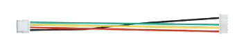 |
| GH1.25-4P → GH1.25-6P cable, 20 cm | 1 | Pixhawk 4 / 5 / 6 telemetry ports |  |
Dimensions & mounting
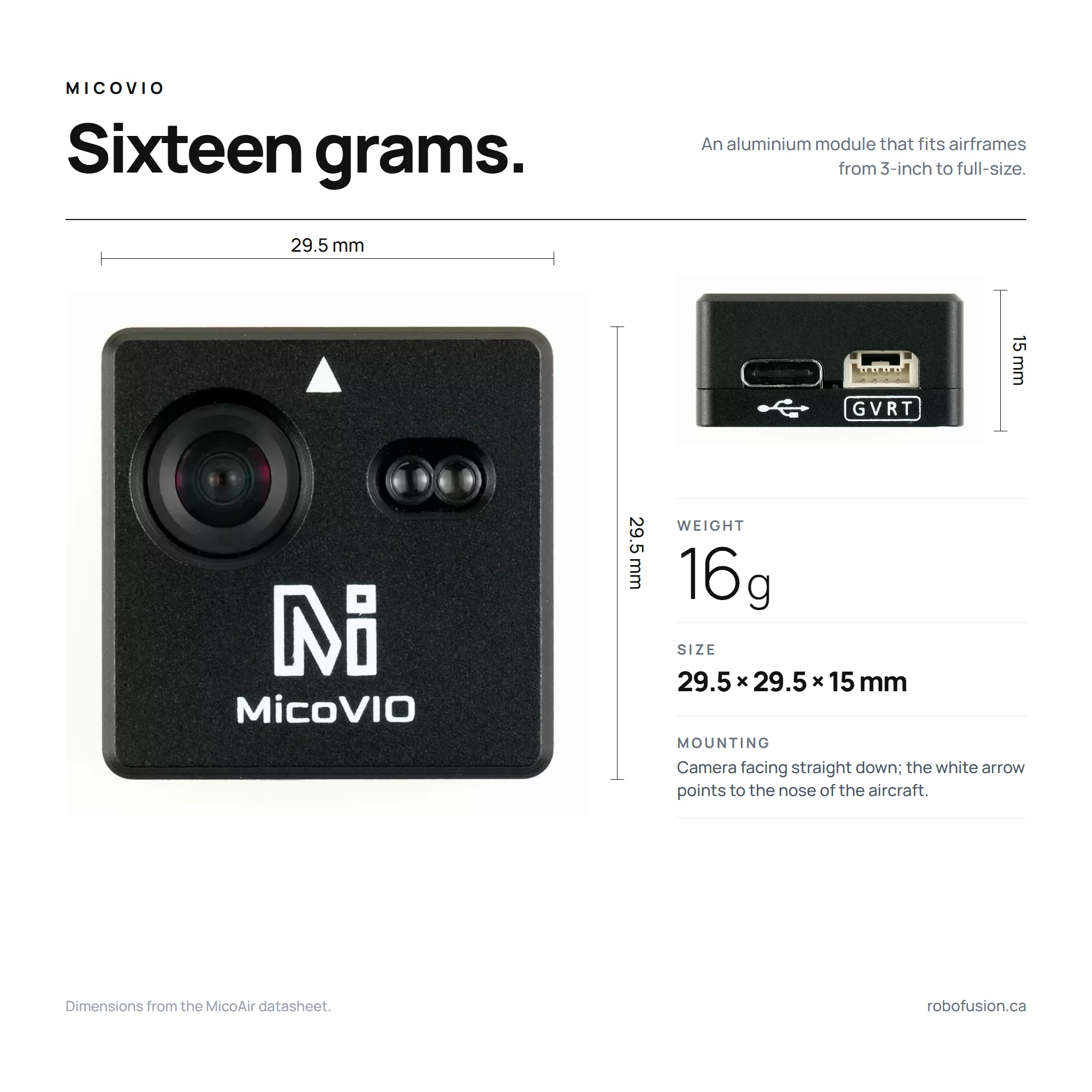
Mount the module camera facing straight down with the white arrow pointing to the nose of the aircraft, as rigidly as the flight controller itself — VIO fuses its own IMU, so a soft or wobbly mount hurts it exactly as vibration hurts the autopilot. Keep the lens and the two ToF windows clear of props, landing gear and cable ties, and do not let the ToF look at a nearby strut. The module boots in about 12 s; let it finish before arming.
Ports & pinout
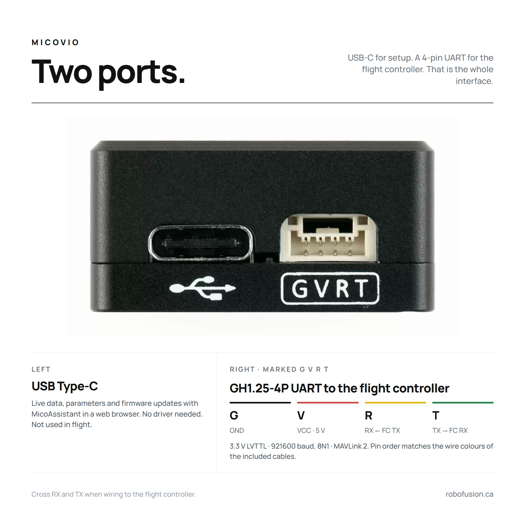
| Pin (case marking) | Signal | Connect to flight controller |
|---|---|---|
| G | GND | GND |
| V | VCC, 5 V | 5 V |
| R | RX (3.3 V) | UART TX |
| T | TX (3.3 V) | UART RX |
The USB Type-C port is for MicoAssistant — live data, parameters and firmware updates in a web browser; it is not needed in flight.
Wiring
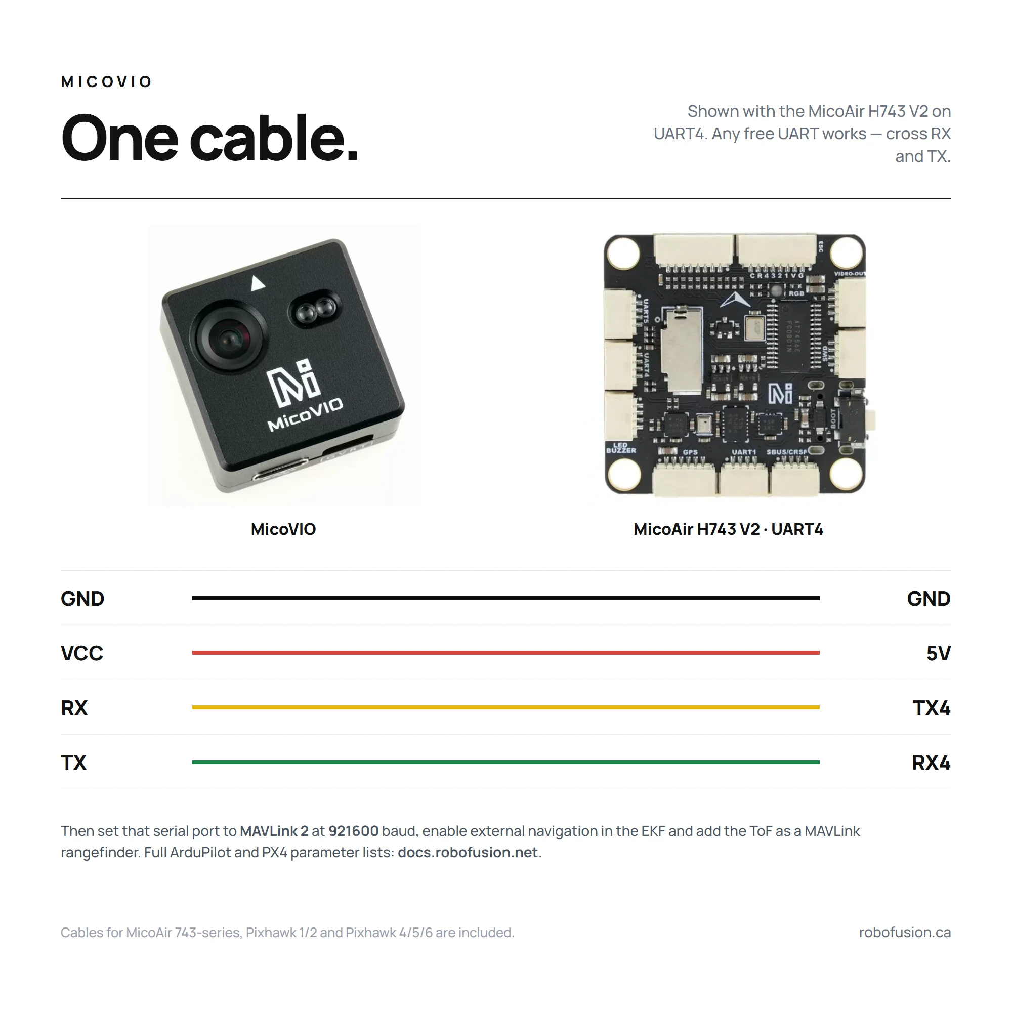
Any free UART works; the diagram shows UART4 on the MicoAir H743 V2. Cross RX and TX, power from a 5 V pad, and note which SERIALn (ArduPilot) or TELEM n (PX4) that port maps to in your flight controller manual or in MicoConfigurator's port page.
The flight controller firmware must include the visual-odometry / external-vision library. H7 boards do — H743 V2, H743 AIO and the NxtPX4 V2 are all fine. Most F405 boards do not (F405 V2, F405 Mini): ArduPilot builds for boards with less than 2 MB of flash normally leave VISO_TYPE out to save space.
Configuration — ArduPilot
Requires ArduPilot 4.5.2 or newer. MicoAir recommends doing this in MicoConfigurator, which exposes every parameter below on its Ports, Sensors → External Vision, Sensors → Rangefinder and EKF pages; Mission Planner's full parameter list works just as well. n is the serial port MicoVIO is wired to.
1 — Serial port
SERIALn_PROTOCOL = 2       # MAVLink 2
SERIALn_BAUD     = 921     # 921600
SERIALn_OPTIONS  = 1024    # ArduPilot 4.6 and earlier: don't forward MAVLink on this port
MAVn_OPTIONS     = 2       # ArduPilot 4.7 and later: the same "don't forward" option moved here
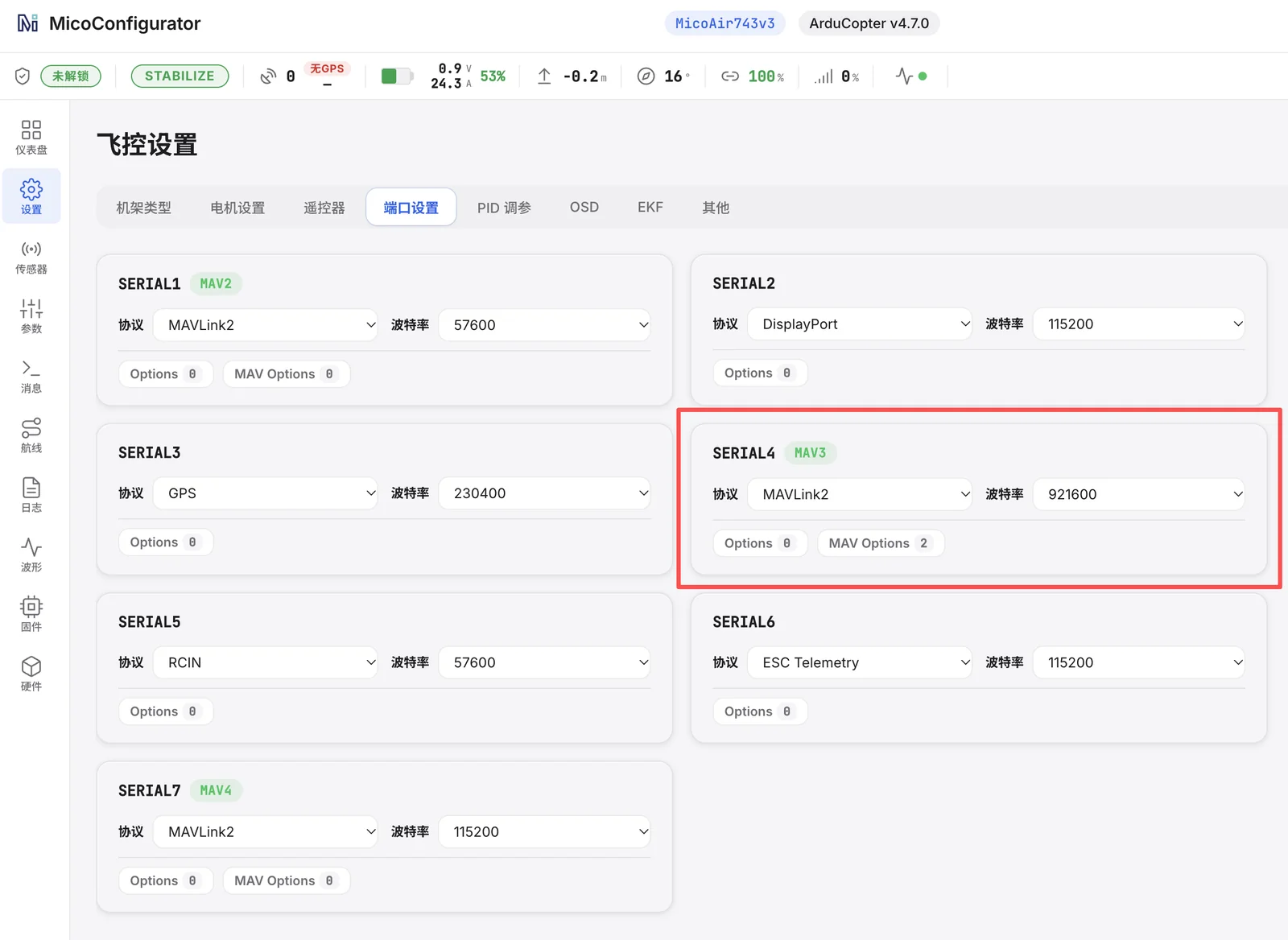 MicoConfigurator → Settings → Ports: the MicoVIO port set to MAVLink 2, 921600, MAV Options 2 (ArduPilot 4.7). Screenshot from the Chinese UI; the English UI has the same layout.
2 — Visual odometry
VISO_TYPE      = 3         # ODOMETRY-message source (listed as "VOXL" in the parameter docs — the same message format)
VISO_YAW_M_NSE = 0.1
Leave the other VISO_ parameters at their defaults and reboot the flight controller.
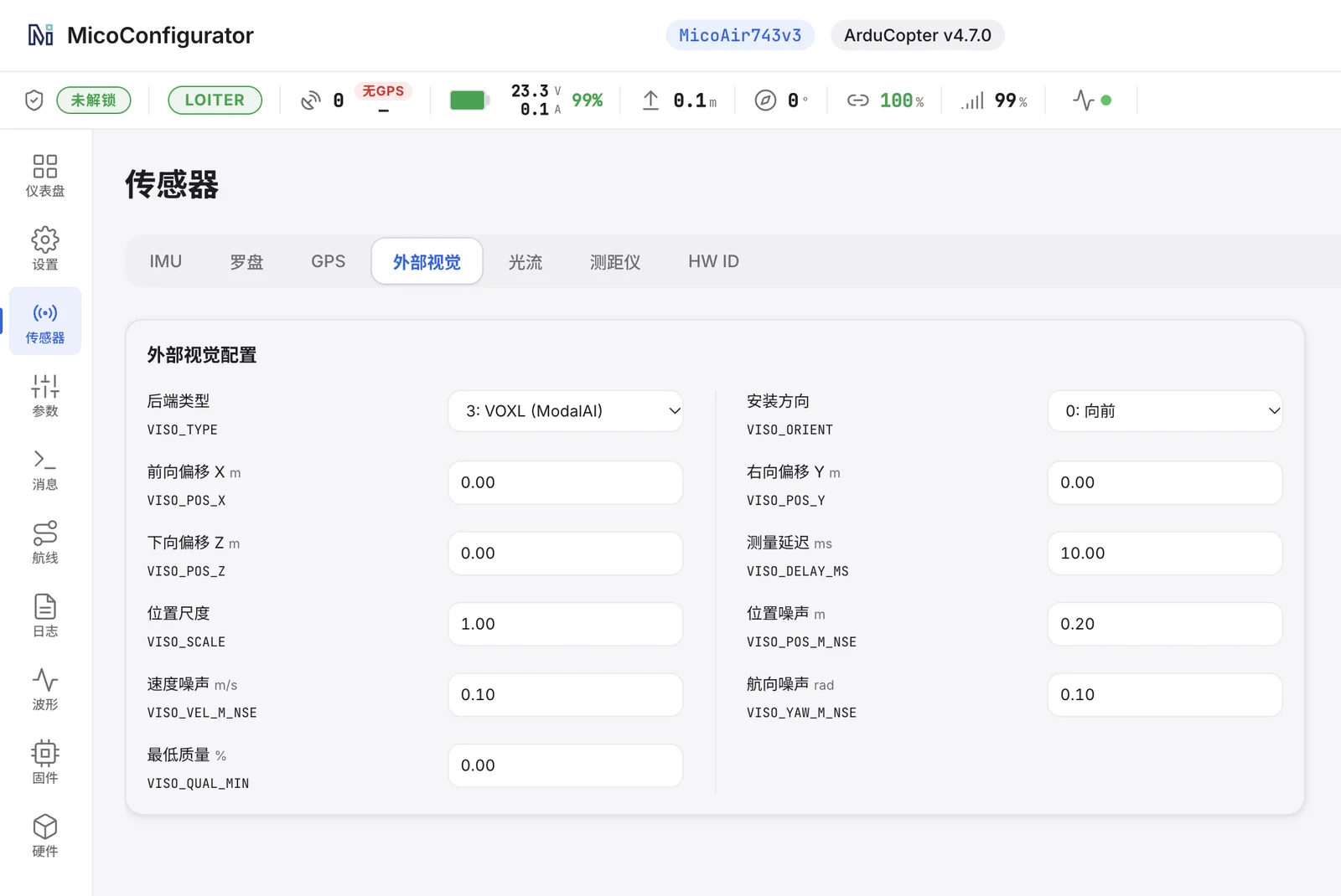 Sensors → External Vision:
 VISO_TYPE 3, VISO_YAW_M_NSE 0.10, everything else default.
3 — Rangefinder (the ToF arrives as a MAVLink DISTANCE_SENSOR)
RNGFND1_TYPE   = 10        # MAVLink
RNGFND1_MAX_CM = 1200      # ArduPilot 4.6 and earlier (centimetres)
RNGFND1_MIN_CM = 1
RNGFND1_MAX    = 12        # ArduPilot 4.7 and later (metres)
RNGFND1_MIN    = 0.01
RNGFND1_ORIENT = 25        # down
Reboot or refresh parameters after setting RNGFND1_TYPE.
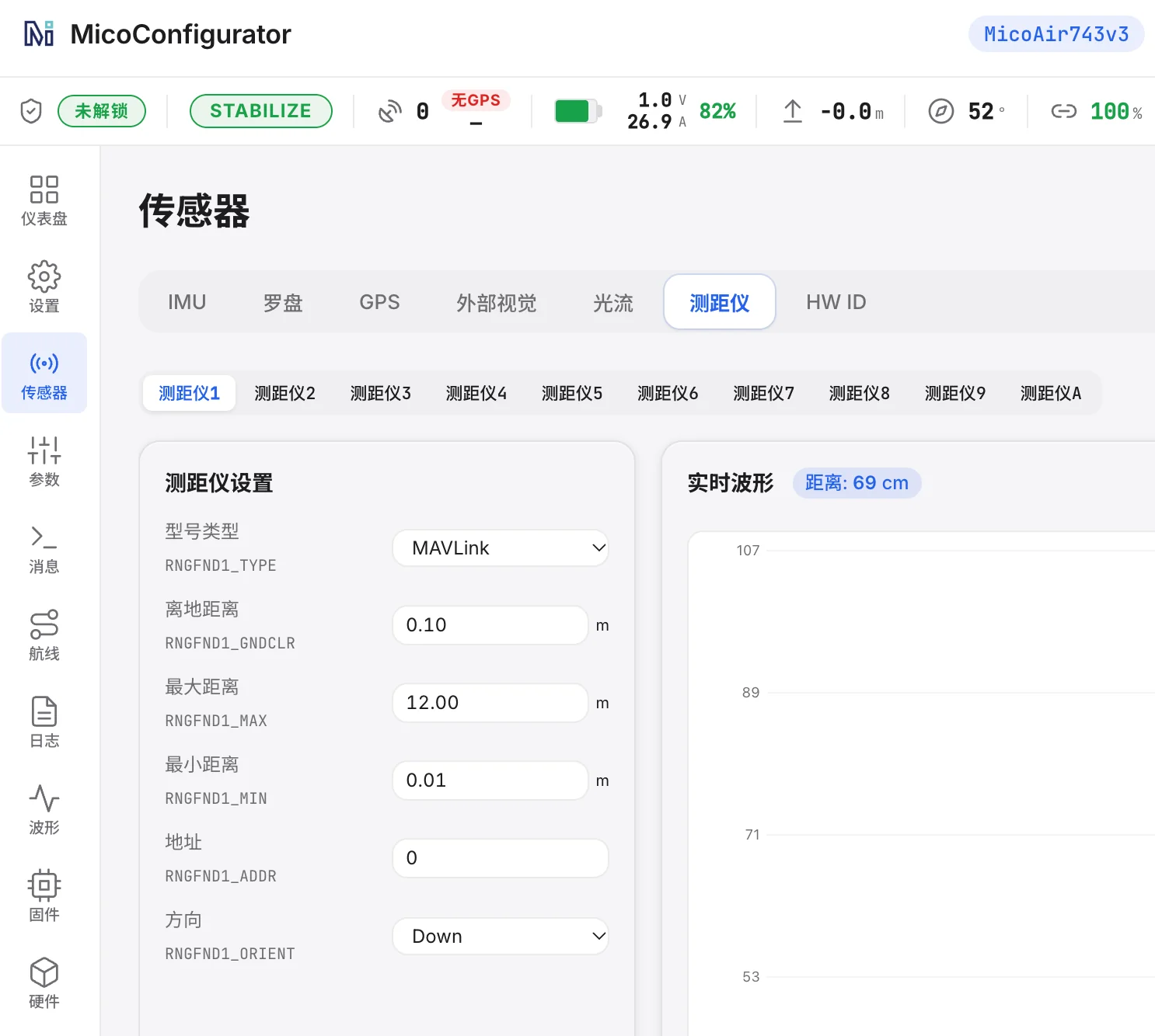 Sensors → Rangefinder: type MAVLink, 12 m / 0.01 m, orientation Down — the live waveform confirms the ToF is arriving.
4 — EKF sources
EK3_SRC1_POSXY = 6         # ExternalNav
EK3_SRC1_POSZ  = 2         # RangeFinder
EK3_SRC1_VELXY = 6         # ExternalNav
EK3_SRC1_VELZ  = 6         # ExternalNav
EK3_SRC1_YAW   = 6         # ExternalNav (or 1 = Compass if you fly with a good compass — keep VISO_TYPE = 3 either way)
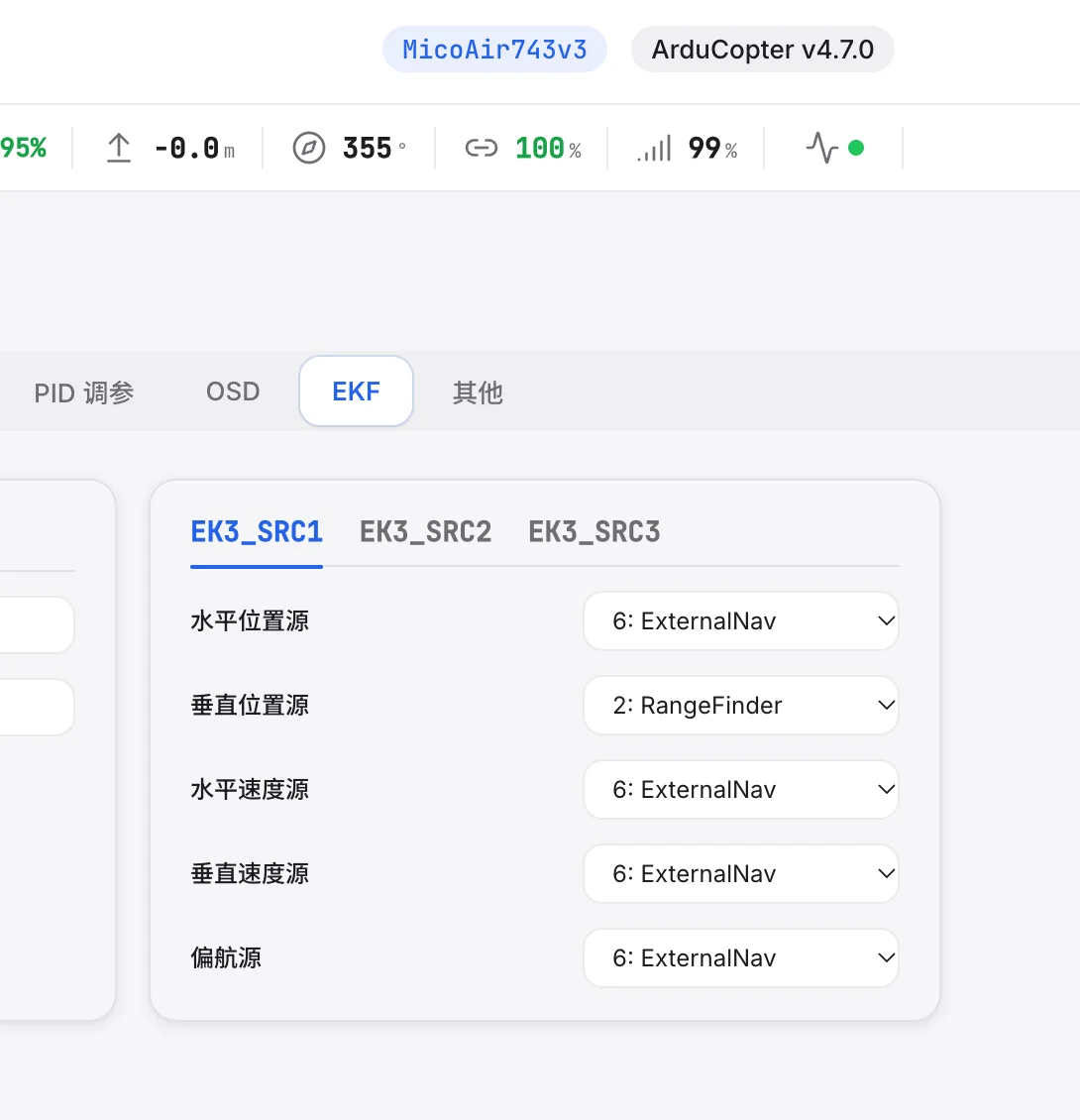 Settings → EKF → EK3_SRC1: horizontal position, horizontal velocity, vertical velocity and yaw from ExternalNav; vertical position from the rangefinder.
Check it: in Mission Planner's MAVLink Inspector (or MicoConfigurator's Messages page) you should see ODOMETRY at roughly 40 Hz and DISTANCE_SENSOR at about 43 Hz once the module has booted. Hover first in Loiter over a textured floor; the aircraft should sit still without stick input.
Configuration — PX4
1 — Serial port (example: MicoVIO on TELEM 2)
MAV_1_CONFIG  = TELEM 2    # the port MicoVIO is wired to — reboot after changing
MAV_1_MODE    = Onboard
MAV_1_FORWARD = Disabled
SER_TEL2_BAUD = 921600 8N1
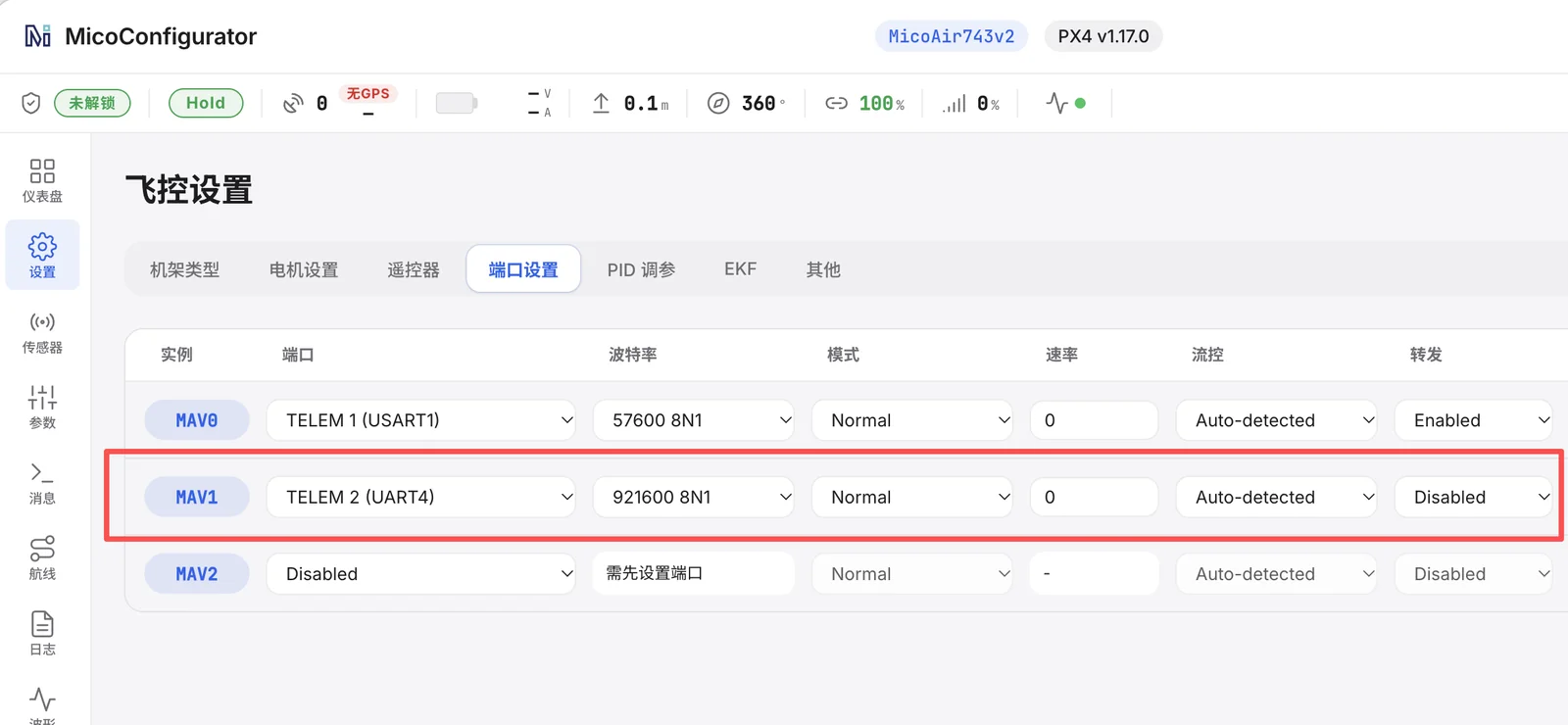 PX4 ports page: the MAV1 instance assigned to the MicoVIO UART at 921600 8N1 with forwarding disabled.
2 — EKF2
EKF2_EV_CTRL = 9           # bit 0 horizontal position + bit 3 yaw
EKF2_HGT_REF = 2           # Range sensor
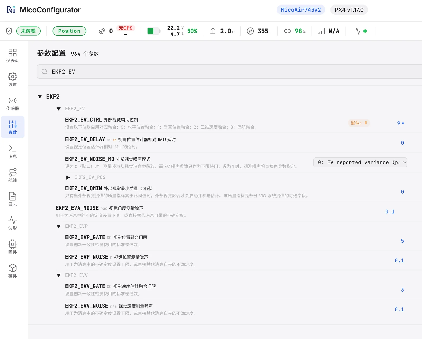 Parameters → search
 EKF2_EV: EKF2_EV_CTRL = 9; the other external-vision parameters stay at their defaults.
EKF2_EV_CTRL is a bitmask: 0 = horizontal position, 1 = vertical position, 2 = 3D velocity, 3 = yaw. MicoAir's recommended value 9 fuses horizontal position and yaw from the module and takes height from the ToF. In QGroundControl's MAVLink Inspector, ODOMETRY should stream at about 40 Hz; then test in Position mode.
Testing with MicoAssistant
Connect the USB Type-C port to a computer and open MicoAssistant in a Chromium browser — no driver is normally needed; pick the module's serial port and any baud rate. The Data page shows tracking state, VIO quality (0–100), receive rate, position, body-frame velocity, attitude and ToF distance, live waveforms and an XY trace of where the module thinks it has moved. Wave it over a textured surface and watch the trace follow your hand before you ever put it on an aircraft. Firmware updates are done from the same tool.
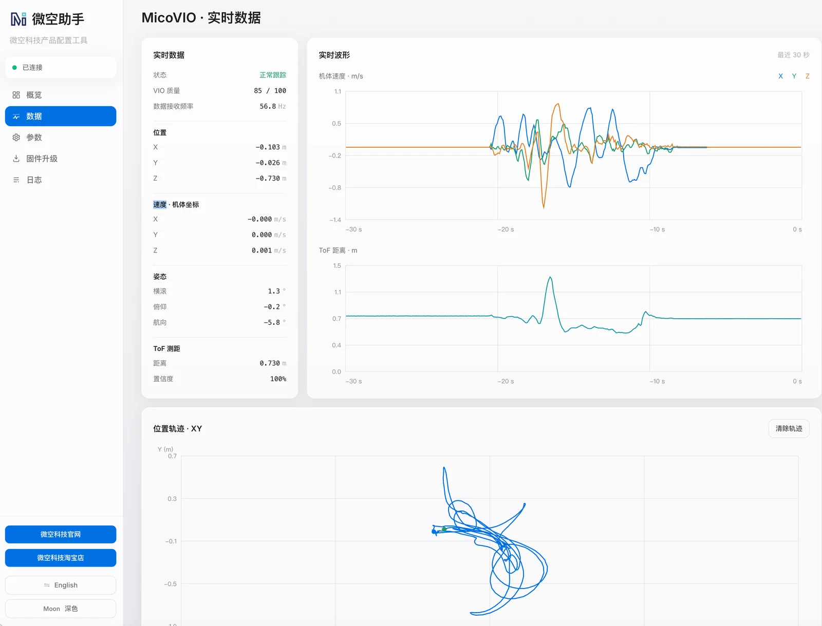 MicoAssistant → Data while the module is tracking: quality 85/100 at 56.8 Hz, position and velocity, ToF distance and the XY trace of the module's movement. Chinese UI shown; the English UI is identical.
Operating limits — read before the first flight
- Light: needs more than ~1 lux. Dim rooms are fine; a dark hangar is not — add a downward light and it will track in tunnels and mines.
- Texture: like any camera, it needs something to look at. A glossy uniform floor, still water or a perfectly plain carpet starve it of features; even so, it is far more forgiving than optical flow on low-texture and reflective surfaces.
- Height: initialise from as low as 1 cm; working height up to 30 m depending on texture and light. The ToF gives 12 m in shade and about 8 m in full sun — above that the EKF height source switches to the barometer.
- Speed and rotation: 10 m/s typical at 2 m height, 60° tilt, 300°/s. It is designed to survive spins and "dish-pan" orbit flight that would blind an optical flow sensor.
- Boot: about 12 s to first data. Don't arm before the
ODOMETRYstream appears. - Accuracy drifts with distance: ~1 % typical. Over a 100 m flight expect roughly a metre; loop closure keeps a hover tight, it does not make the sensor absolute. For centimetre-level absolute position outdoors you still want RTK.
FAQ
What is the MicoVIO and what does it do?
A 16-g module with a global-shutter camera, IMU and ToF rangefinder that fuses them on board and sends relative position, velocity and attitude to the flight controller as MAVLink 2 ODOMETRY. ArduPilot and PX4 drones can hover, hold position, fly waypoints and return to launch with it where there is no GPS.
How is it different from an optical flow sensor like the MTF-01? Optical flow gives the autopilot a horizontal velocity; position is integrated from it and drifts. MicoVIO estimates full 6-DoF motion directly, stays locked through fast rotation thanks to the IMU, and adds local loop closure so a hover does not wander. Typical trajectory error is about 1 % of distance flown. Full comparison: VIO vs Optical Flow.
Which flight controllers work? ArduPilot ≥ 4.5.2 and PX4 on boards whose firmware includes external-vision support — H7 boards such as the H743 V2, H743 AIO and NxtPX4 V2. Most F405 boards do not.
Do I need a companion computer or ROS? No. Everything runs inside the 16-gram module. The traditional way to get VIO on an open-source drone is a stereo or tracking camera (Intel RealSense D435 or T265) plus a Raspberry Pi or Jetson running ROS — several hundred dollars, well over 100 g, and days of integration. MicoVIO replaces all of that with one UART cable and a handful of flight controller parameters.
Does it work outdoors and in low light? Yes, within limits: from ~1 lux, in bright sun, up to 30 m, with the ToF reaching ~8 m in full sun and 12 m in shade. Total darkness needs an added light.
When can I buy it? First North American batch expected late October to mid-November 2026. Reserve by emailing info@robofusion.net.
Related guides
- VIO vs Optical Flow — what's the difference?
- Optical Flow Setup Guide (MTF-01 / 01P / 02 / 02P) — the lighter, cheaper option for simple indoor hover
- MicoAir H743 V2 — User Manual · NxtPX4 V2 — User Manual
- ArduPilot Basic Configuration · PX4 Build & Configuration Walkthrough
- What Is RTK? — when you need absolute centimetre accuracy outdoors instead
Written and maintained by the Robofusion engineering team. Specifications from the MicoAir MicoVIO datasheet and user manual, 15 October 2026.