MicoAir MA-RTK Series — User Manual
The MicoAir MA-RTK series is a complete centimeter-level RTK positioning system for UAVs, robots and drone light shows: three airborne rover modules at three price/performance points, plus a self-contained battery-powered base station that generates the corrections. All rovers include an IST8310 compass, plug into any ArduPilot or PX4 flight controller over UART + I2C, and ship with a quad-helix antenna and full cable set.
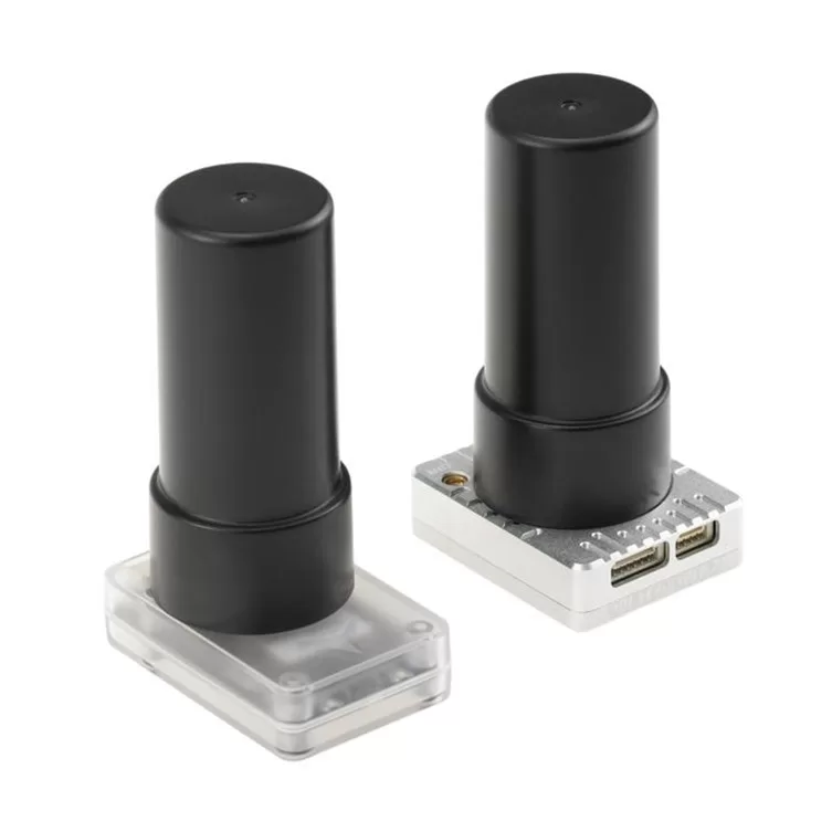
New to RTK? Read What Is RTK? — the plain-English explainer first. To put the system on the air, follow the RTK Setup Guide.
The family at a glance
| MA-RTK-AIR-982 | MA-RTK-AIR-626 | MA-RTK-AIR-F9P | |
|---|---|---|---|
| Positioning tier | Full-band flagship | Cost-effective | Proven u-blox |
| GNSS receiver | Unicore UM982 | Unicore UM626N | u-blox ZED-F9P |
| Bands | L1 + L2 + L5 | L1 + L5 | L1 + L2 |
| RTK accuracy | 0.8 cm + 1 ppm (H) / 1.5 cm + 1 ppm (V) | 1.5 cm + 1 ppm | 1.0 cm + 1 ppm |
| Max update rate | 20 Hz | 10 Hz | 8 Hz RTK / 10 Hz single |
| Max satellites | 28 (single) / 50+ (RTK) | 36 | 32 |
| Dual-antenna heading | Yes (optional 2nd antenna) | No | No |
| Compass | IST8310 | IST8310 | IST8310 |
| Protocol | NMEA-0183 | UBX | UBX / NMEA-0183 |
| Firmware | ArduPilot / PX4 | ArduPilot only | ArduPilot / PX4 |
| Power | 700 mW | 200 mW | 350 mW |
| Size / weight | 39 × 31.5 × 16 mm · 20 g | 44 × 29 × 14.7 mm · 13 g | 44 × 29 × 14.7 mm · 13 g |
(weights are without the antenna)
Which one should you buy?
- MA-RTK-AIR-982 — the one to get if you want the best: triple-band means the fastest FIX and the most robust lock near obstructions, 20 Hz output feeds fast vehicles, and it's the only one with dual-antenna GNSS heading — the killer feature for flying near steel structures, or any build where the magnetic compass struggles. PX4 users wanting heading: this is your module.
- MA-RTK-AIR-626 — the fleet module. It gives up L2, GLONASS G2 and PX4 support to hit a price where equipping 20 or 200 light-show drones is realistic, while still reaching a real centimeter-grade FIX on ArduPilot.
- MA-RTK-AIR-F9P — the safe, battle-tested choice. The u-blox ZED-F9P is the best-documented RTK chip in the hobby/industrial world, speaks native UBX to both firmwares, and slots into any workflow that already expects u-blox (u-center, existing F9P bases).
- MA-RTK-BASE — you need one correction source per site (not per drone). One base serves an unlimited number of rovers within radio range. If you already have any RTCM3 base or an NTRIP subscription, the rovers will accept that instead.
Where to buy
All four ship worldwide from the Robofusion Hong Kong warehouse:
- MA-RTK-AIR-982 — UM982 triple-band RTK, dual-antenna heading — single-antenna or Dual-Antenna Kit
- MA-RTK-AIR-626 — budget RTK for swarms & light shows
- MA-RTK-AIR-F9P — u-blox ZED-F9P RTK module
- MA-RTK-BASE Kit — base station with tripod & antenna
- Add a LR900-F 915 MHz telemetry radio pair for the direct-broadcast correction link.
MA-RTK-AIR-982
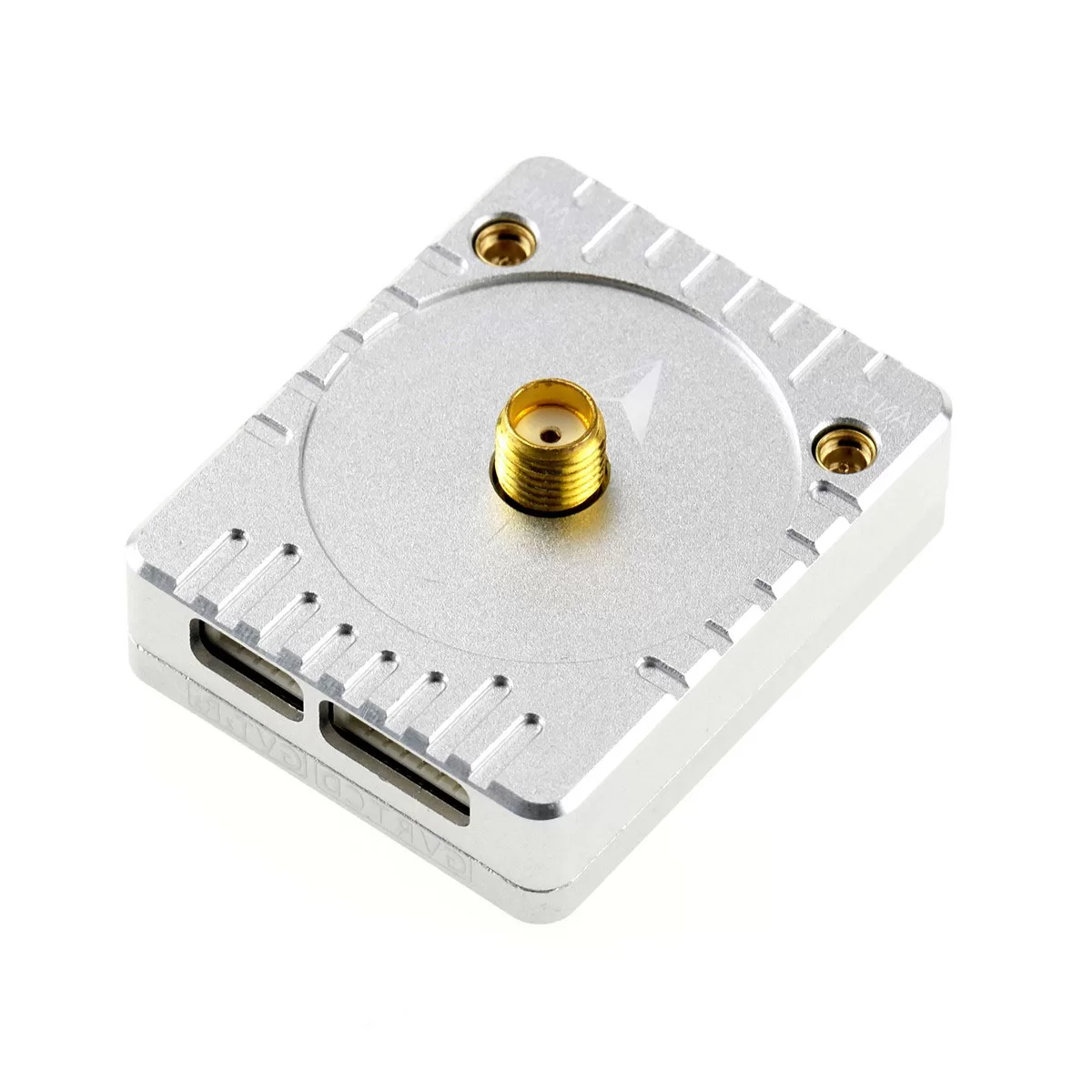
Triple-band (L1+L2+L5) rover on the Unicore UM982 — the full-performance option, and the only module in the family with dual-antenna GNSS heading.
Specifications
| Item | Specification |
|---|---|
| GNSS receiver | Unicore UM982 |
| Bands | L1 + L2 + L5 |
| Signals | GPS L1C/A, L2P*/L2C, L5* · BDS B1I, B2I, B3I · GLONASS G1, G2 · Galileo E1, E5a*, E5b · QZSS L1, L2, L5* (* primary antenna only) |
| RTK accuracy | Horizontal 0.8 cm + 1 ppm · Vertical 1.5 cm + 1 ppm |
| Single-point accuracy | 1.5 m |
| Max navigation rate | 20 Hz |
| Max satellites used | 28 (single-point) / 50+ (RTK) |
| Compass | IST8310 (I2C) |
| Output protocol | NMEA-0183 (factory default: no output until configured by autopilot) |
| UART baud | 115200 default, auto-raised to 230400 by the autopilot |
| Supply | 4–5 V · 700 mW |
| Antenna interfaces | MMCX × 2 (ANT1 primary / ANT2 secondary) + SMA × 1 — see the note below |
| Data interfaces | GH1.25-6P (FC) + GH1.25-4P (RTCM in / second UART) |
| Dimensions / weight | 39 × 31.5 × 16 mm · 20 g |
| Firmware | ArduPilot / PX4 |
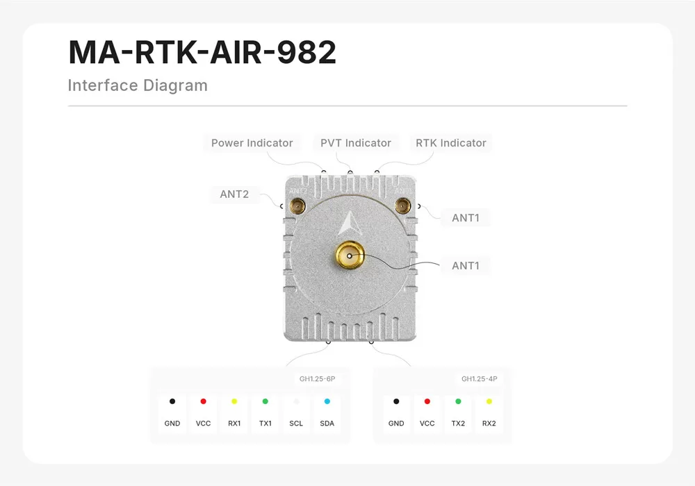
The primary antenna can be attached either to the ANT1 SMA connector or to the ANT1 MMCX connector. They are two ways into the same receiver input, not two inputs: never connect an antenna to both at once. ANT2 (MMCX) is the secondary antenna, and is only connected when you want dual-antenna heading.
| Connector | Role | Notes |
|---|---|---|
| ANT1 SMA | primary antenna | alternative to ANT1 MMCX — one or the other |
| ANT1 MMCX | primary antenna | alternative to ANT1 SMA — one or the other |
| ANT2 MMCX | secondary antenna | connect only for dual-antenna heading |
Package (single-antenna): module ×1, quad-helix antenna ×1, GH1.25-6P cable 20 cm, SH1.25-6P FC cable 20 cm, GH1.25-4P cable 10 cm. Dual-Antenna Kit: module ×1, cables as above, plus 2 × quad-helix antenna with 40 cm feeder line and support rod — everything needed for GNSS heading. Mount the two antennas along the airframe with at least 20 cm of separation (more is better) with ANT1 toward the nose. See dual-antenna setup.
MA-RTK-AIR-626
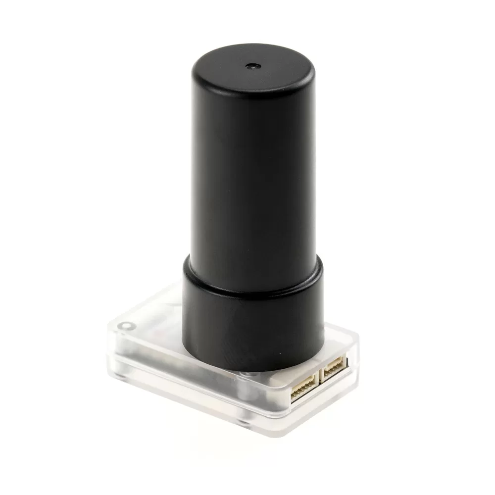
Dual-band (L1+L5) rover on the Unicore UM626N — deliberately cost-optimized for drone swarms and light shows, where every aircraft needs a centimeter fix but the bill multiplies by the fleet size.
Specifications
| Item | Specification |
|---|---|
| GNSS receiver | Unicore UM626N |
| Bands | L1 + L5 |
| Signals | GPS L1C/A, L5 · BDS B1I, B2a · GLONASS G1 · Galileo E1, E5a · QZSS L1, L5 |
| RTK accuracy | 1.5 cm + 1 ppm |
| Single-point accuracy | 1.5 m |
| Max navigation rate | 10 Hz |
| Max satellites used | 36 |
| Compass | IST8310 (I2C) |
| Output protocol | UBX (u-blox-compatible) |
| UART baud | 115200 fixed (not configurable) |
| Supply | 4–5 V · 200 mW |
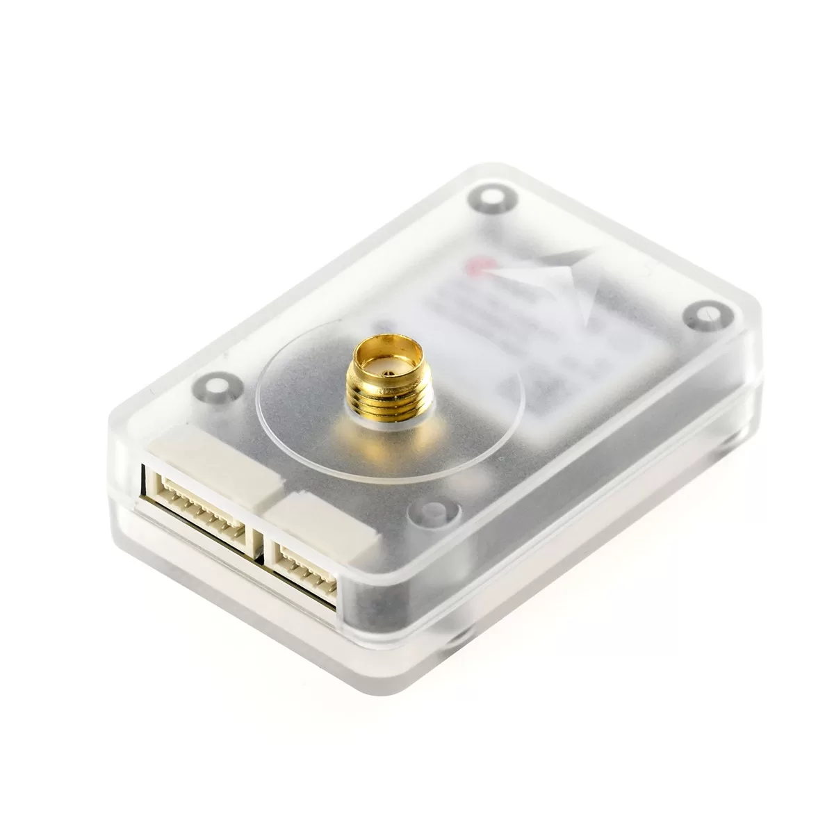
| Antenna interface | SMA × 1 |
| Data interfaces | GH1.25-6P (FC) + GH1.25-4P (RTCM in) |
| Dimensions / weight | 44 × 29 × 14.7 mm · 13 g |
| Firmware | ArduPilot only — PX4 not currently supported |
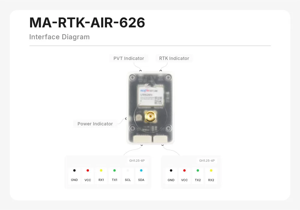
Package: module ×1, quad-helix antenna ×1, GH1.25-6P cable 20 cm, SH1.25-6P FC cable 20 cm, GH1.25-4P cable 10 cm.
MA-RTK-AIR-F9P
Dual-band (L1+L2) rover on the u-blox ZED-F9P — the most widely deployed and best-documented RTK receiver in the drone world, wrapped in the same form factor and cable set as the 626.
Specifications
| Item | Specification |
|---|---|
| GNSS receiver | u-blox ZED-F9P |
| Bands | L1 + L2 |
| Signals | GPS L1C/A, L2C · BDS B1I, B2I · GLONASS G1, G2 · Galileo E1, E5b · QZSS L1, L2 |
| RTK accuracy | 1.0 cm + 1 ppm |
| Single-point accuracy | 1.5 m |
| Max navigation rate | 8 Hz (RTK) / 10 Hz (single-point) |
| Max satellites used | 32 |
| Compass | IST8310 (I2C) |
| Output protocol | UBX / NMEA-0183 |
| UART baud | 38400 default, auto-raised to 230400 by the autopilot |
| Supply | 4–5 V · 350 mW |
| Antenna interface | SMA × 1 |
| Data interfaces | GH1.25-6P (FC) + GH1.25-4P (RTCM in) |
| Dimensions / weight | 44 × 29 × 14.7 mm · 13 g |
| Firmware | ArduPilot / PX4 |
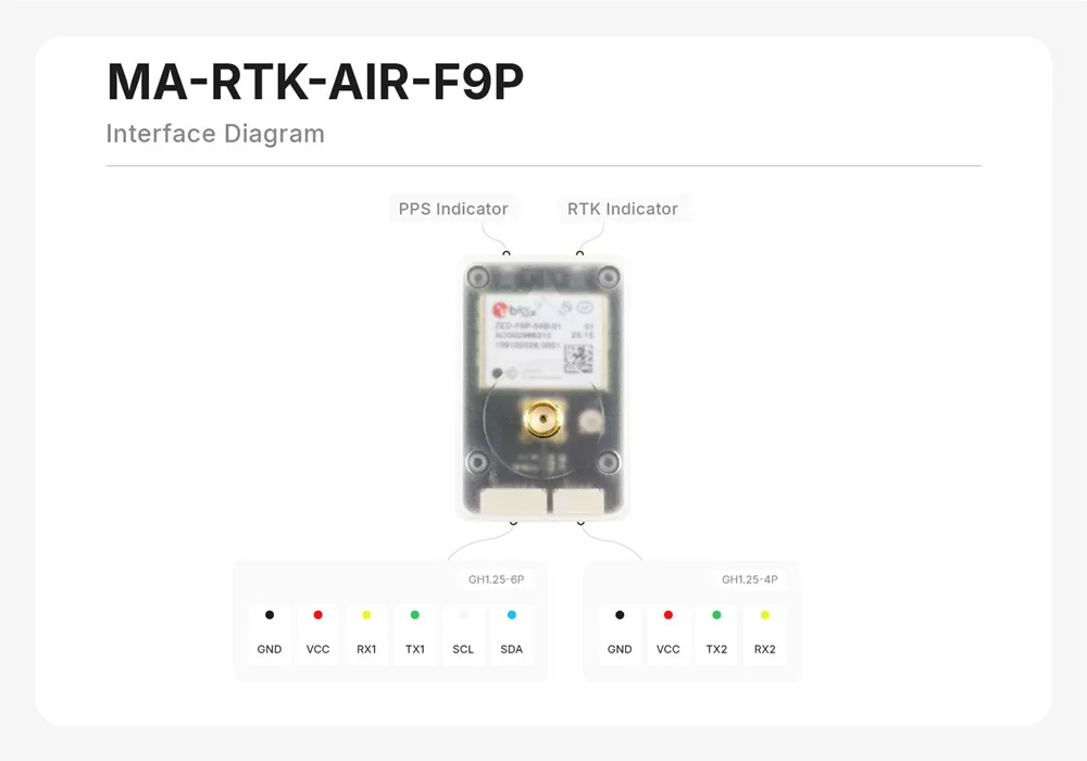
Package: module ×1, quad-helix antenna ×1, GH1.25-6P cable 20 cm, SH1.25-6P FC cable 20 cm, GH1.25-4P cable 10 cm.
MA-RTK-BASE
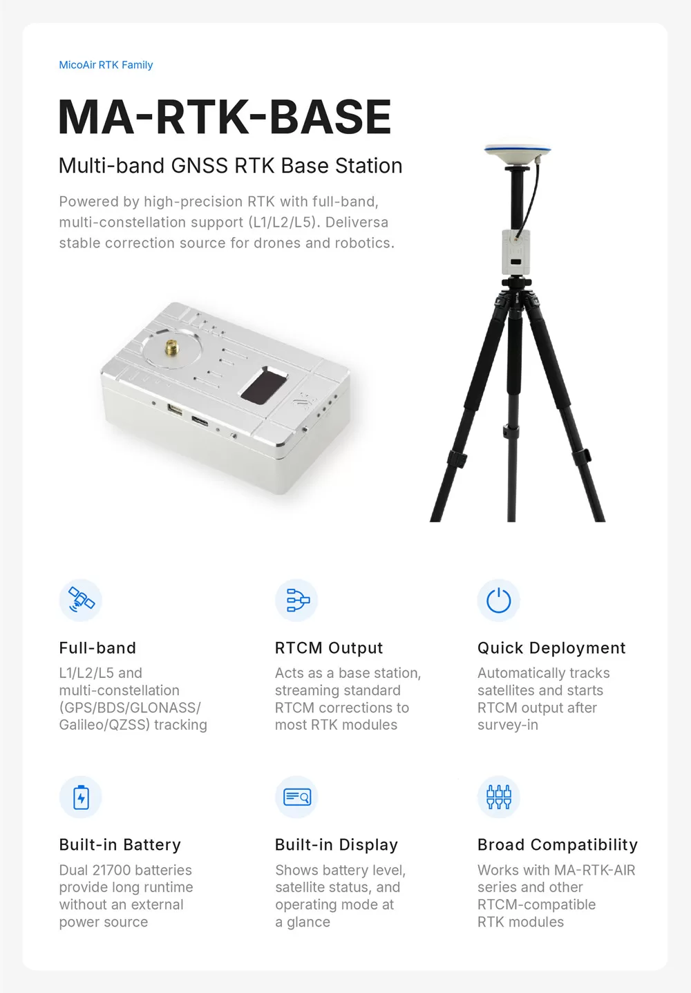
A self-contained, battery-powered RTK base station on the same UM982 triple-band receiver as the flagship rover. Power it on, give it sky view, and it starts emitting standard RTCM3 corrections on both USB-C and UART — no laptop-side configuration, no survey software required. One base serves any number of rovers.
Specifications
| Item | Specification |
|---|---|
| GNSS receiver | Unicore UM982 (L1+L2+L5) |
| Output | RTCM3 corrections at 1 Hz |
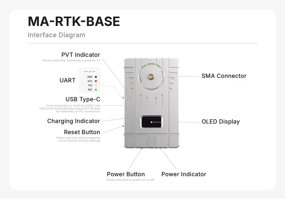
| Ports | USB Type-C (UART1) + GH1.25-4P (UART2) — both stream RTCM simultaneously |
| Baud | 115200 on both ports |
| USB-serial chip | CH340 (driver needed on Windows) |
| Display | OLED status screen — NO FIXED → 3D → RTK BASE |
| Battery | 2 × 21700 Li-ion, 5000 mAh each — ≈ 12 h runtime with active antenna + 1 W radio |
| Charging | USB-C, 10 W max (5 V / 2 A) |
| Controls | Power button (hold to switch on/off) · Reset button (hold while powering on = factory reset) |
| Indicators | PVT LED (solid = position fix) · charge LED · power LED |
Kit contents: base module ×1, tripod ×1, multi-band GNSS mushroom antenna ×1, antenna feeder cable ×1, USB-C to USB-C cable 2 m ×1, mounting hardware ×1.
Both ports run at 115200 with a 1 Hz RTCM output, and the receiver has already been set up for base-station duty. Those settings can be changed with Unicore's UPrecise tool, but doing so is genuinely easy to get wrong and is not something to try without GNSS receiver experience — a base emitting the wrong RTCM message set will leave every rover stuck in FLOAT with no obvious symptom.
Wiring the rover to the flight controller
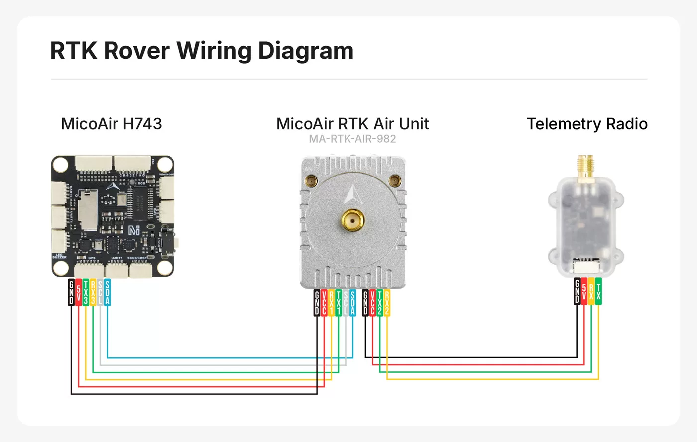
Every rover uses the same two connectors:
GH1.25-6P — main port, to the flight controller:
| Pin | Function | Connect to FC |
|---|---|---|
| GND | Ground | GND |
| VCC | 4–5 V in | 5 V / 4V5 |
| RX1 | UART receive | a spare UART TX (e.g. TX3) |
| TX1 | UART transmit | that UART's RX (e.g. RX3) |
| SCL | I2C clock (IST8310 compass) | SCL |
| SDA | I2C data (IST8310 compass) | SDA |
GH1.25-4P — auxiliary port (GND · VCC · TX2 · RX2): a second UART. Its job is to receive RTCM corrections directly from a telemetry radio in direct-broadcast mode — wire radio TX → RX2, radio RX → TX2. Using ground-station relay instead? Leave this port unplugged.
Mount the quad-helix antenna vertically on a mast, highest point of the airframe, with nothing above it — and as far as practical from VTX/HD air units, ESC power wiring and motors. On the 982 Dual-Antenna Kit, both antennas need equally clean sky: baseline ≥ 20 cm, ANT1 forward.
ArduPilot configuration
Connect the 6P cable to (say) SERIAL3/GPS1 and set, per model:
MA-RTK-AIR-F9P — plug and play. Leave GPS_TYPE=1 (AUTO); ArduPilot detects the F9P and configures it, raising the baud to 230400 automatically.
MA-RTK-AIR-626:
GPS_AUTO_CONFIG = 0 # module is pre-configured; don't overwrite
Leave everything else at its default. Refresh parameters after writing; the module is then recognized as a u-blox-protocol GPS.
MA-RTK-AIR-982 (single antenna):
GPS1_TYPE    = 24       # UnicoreNMEA
GPS1_RATE_MS = 100      # 10 Hz
MA-RTK-AIR-982 (dual antenna / GPS yaw):
GPS1_TYPE      = 25     # UnicoreMovingBaselineNMEA
GPS1_RATE_MS   = 100    # 10 Hz
GPS1_MB_TYPE   = 1      # RelativeToCustomBase — enables the baseline offsets
GPS1_MB_OFS_X  = ...    # ANT1 relative to ANT2, forward positive, metres
GPS1_MB_OFS_Y  = ...    # ANT1 relative to ANT2, right positive, metres
GPS1_MB_OFS_Z  = ...    # ANT1 relative to ANT2, down positive, metres
EK3_SRC1_YAW   = 2      # yaw from GPS
GPS1_MB_OFS_X/Y/Z is the vector from ANT2 to ANT1 in body axes (X forward, Y right, Z down) — this is what actually turns the two antennas into a heading, so it has to be measured and entered. Two antennas 30 cm apart with ANT1 directly in front of ANT2 give X = 0.30, Y = 0, Z = 0. GPS1_MB_TYPE must be set first; the offset sub-parameters only appear after you refresh parameters or reconnect.
Optionally also set GPS1_POS_X/Y/Z — that is a different measurement: ANT1's position relative to the airframe's centre of gravity, which improves position quality when the vehicle rotates on the spot. Leave it at 0 if ANT1 sits close to the CG or you cannot measure it accurately.
Full walkthrough including verification: RTK Setup Guide — dual-antenna heading.
ArduPilot 4.6 and later use GPS1_TYPE, GPS1_MB_TYPE, GPS1_MB_OFS_X/Y/Z and GPS1_POS_X/Y/Z. On 4.5 and earlier the same parameters are called GPS_TYPE, GPS_MB1_TYPE, GPS_MB1_OFS_X/Y/Z and GPS_POS1_X/Y/Z — note that the instance number moves. If a parameter search comes up empty, try the other spelling before assuming your firmware lacks the feature.
The IST8310 compass appears on I2C for every model (leave COMPASS_DISBLMSK at its default 0 so no compass driver is disabled, run the normal compass calibration — unless you fly the 982 dual-antenna setup, where you may disable compass use entirely).
Set the compass orientation before calibrating — the whole MA-RTK family shares one value, listed in the External Compass Orientation guide.
PX4 configuration
MA-RTK-AIR-F9P — native u-blox: GPS_1_PROTOCOL = 1 (u-blox) (default auto works), done.
MA-RTK-AIR-982:
GPS_1_PROTOCOL = 6              # NMEA (generic)
SER_GPS1_BAUD  = 230400         # or Auto
EKF2_GPS_CTRL                   # tick bit 3, "Dual antenna heading"
GPS_YAW_OFFSET                  # baseline angle from the nose, degrees
EKF2_GPS_CTRL is a bitmask; bit 3 is the one that enables dual-antenna heading fusion. A value of 15 sets bits 0–3 and is the usual "everything on" setting. GPS_YAW_OFFSET is the angle of the ANT2 → ANT1 baseline measured from the nose, increasing clockwise seen from above:
| ANT1 relative to ANT2 | GPS_YAW_OFFSET |
|---|---|
| directly ahead | 0 |
| directly to the right | 90 |
| directly behind | 180 |
| directly to the left | 270 |
Reboot the flight controller after writing these.
MA-RTK-AIR-626 — not supported by PX4 at this time; use ArduPilot.
Status LEDs (rover modules)
| LED | Meaning |
|---|---|
| Power | Supply present |
| PVT | Solid once a 3D position fix is achieved |
| RTK | Indicates correction status — lit/steady when RTK corrections are being applied (FLOAT/FIXED) |
FAQ
Do I need one base station per drone? No — one MA-RTK-BASE serves unlimited rovers simultaneously; RTCM is a broadcast, not a handshake. This is why a light-show fleet needs exactly one base.
Can the rovers use corrections from a non-MicoAir base or NTRIP? Yes. They consume standard RTCM3 from any source — third-party base, NTRIP caster via Mission Planner/QGC, or the MA-RTK-BASE.
Does the 982 work with only one antenna? Yes — single-antenna operation is the default; the second antenna only adds GNSS heading.
Which module for a boat / rover / RC car? Same wiring and parameters apply to ArduRover/ArduBoat. The 982's dual-antenna heading is especially valuable on water, where compasses suffer and GPS-course-over-ground fails at low speed.
What's the difference between this and the MG-F10-C? The MG-F10-C is a high-end standalone module (~1 m). The MA-RTK series adds carrier-phase RTK with a correction source — a different accuracy class (1–2 cm) at a different system cost. The explainer covers when each makes sense.
Written and maintained by the Robofusion engineering team.