Grasshopper5 — Open-Source 5-Inch Long-Range FPV Frame
The Grasshopper5 is a 5-inch FPV frame with an adjustable angle between the rotor plane and the body — 3D-printing-friendly, open-source, and compatible with mainstream FPV hardware and all major open-source firmwares (ArduPilot, INAV, Betaflight). Since release it has passed 1,800+ downloads and 7,500+ collections on MakerWorld, making it one of the most popular printable FPV frames on the platform.
Not all about science, but all about fun.
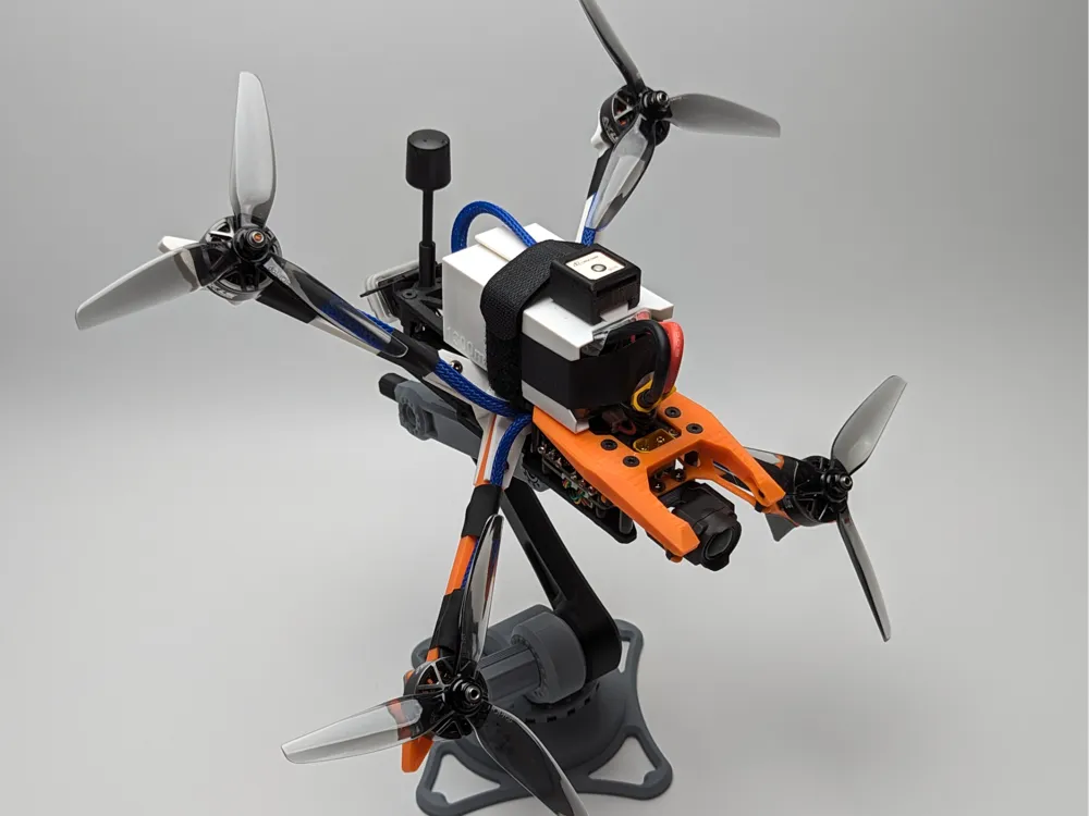
- Frame: free — download the STL + print profile on MakerWorld (assembly PDF included)
- Electronics: the Robofusion 5-Inch FPV Electronics Kit bundles the exact stack this aircraft flies on — H743 FC, 50A ESC, GPS, RC+telemetry, 2.5 W VTX with antenna, and optical flow — for less than buying separately, shipped from Canada
- You add: motors (2207-class), props, an analog FPV camera, and a 6S LiPo
Why a tilted rotor plane?

A conventional quad tilts its whole body forward to fly forward — presenting the airframe's flat face to the airflow and wasting power on drag. Tilting the rotor plane relative to the body (the DJI FPV approach) lets the body stay streamlined while the props do the leaning. The idea isn't new; what didn't exist was a version built for DIY hardware: standard 30.5×30.5 stacks, standard FPV gear, and open firmware. That's the gap the Grasshopper5 fills — with the tilt angle adjustable by swapping two printed parts (20° / 30° / 45°, or design your own).
Honest engineering note: on a 5-inch frame at low Reynolds numbers, the drag savings are modest and partially offset by the tilt mechanism's weight. The 5-inch size is the cheap, fast experimental platform — the layout's real gains appear when scaled to 7-inch, 10-inch and beyond. Validated designs transfer directly.
Features
- Adjustable rotor-plane tilt via two swappable printed parts (20°/30°/45°)
- Fully 3D-printable, or 3D-print + carbon-fiber hybrid for higher performance
- Standard 30.5×30.5 and 20×20 mounts — fits 90%+ of FPV stacks
- DJI-AVATA-2-style damping-ball camera isolation for clean video
- Purpose-placed mounts for GPS, compass, optical flow and rangefinder — positions chosen by flight testing for minimal interference
- Full autonomy support with ArduPilot: GPS hold, waypoint missions, RTL, auto-landing, optical-flow position hold
The build
Camera mounting
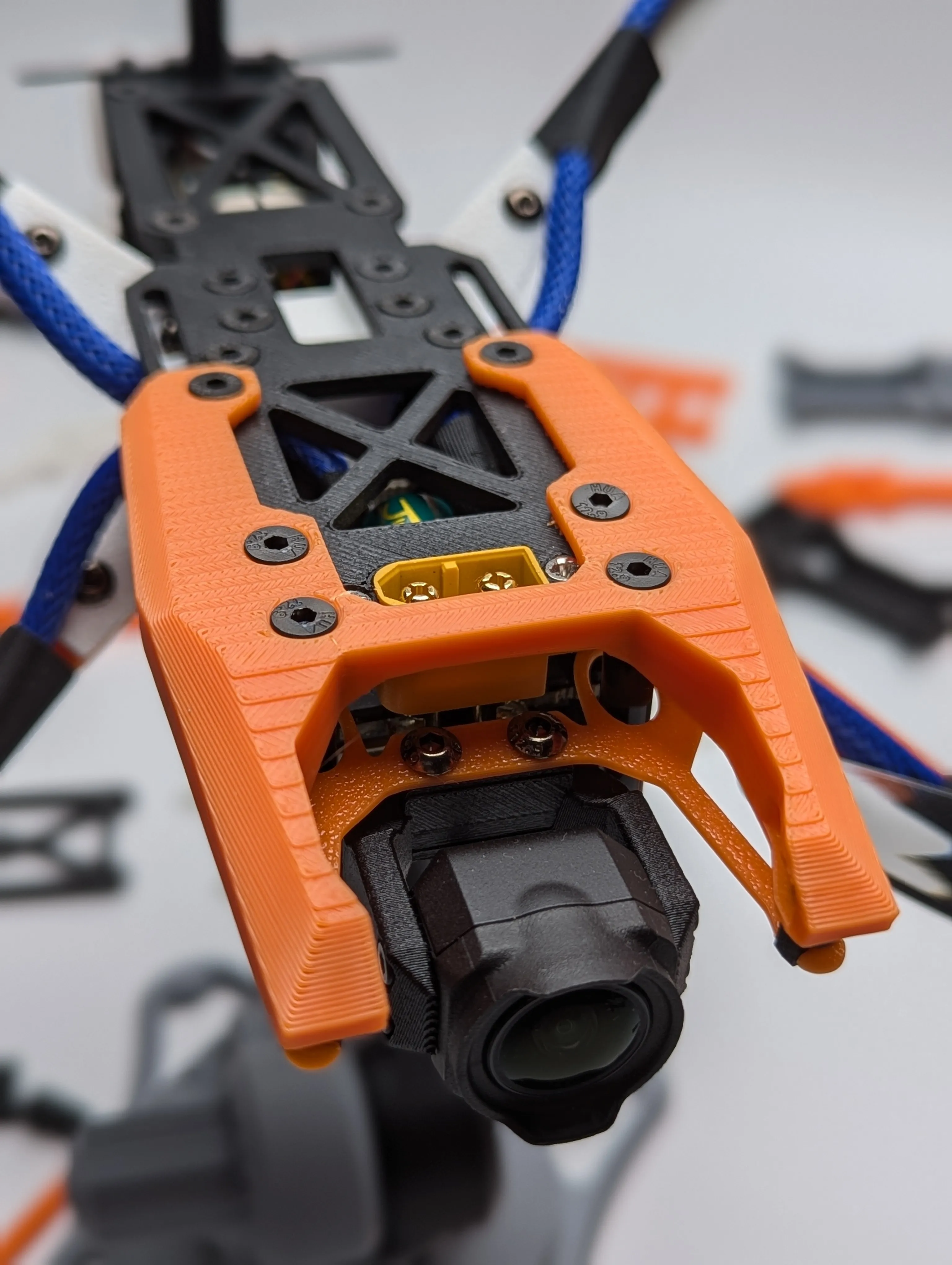
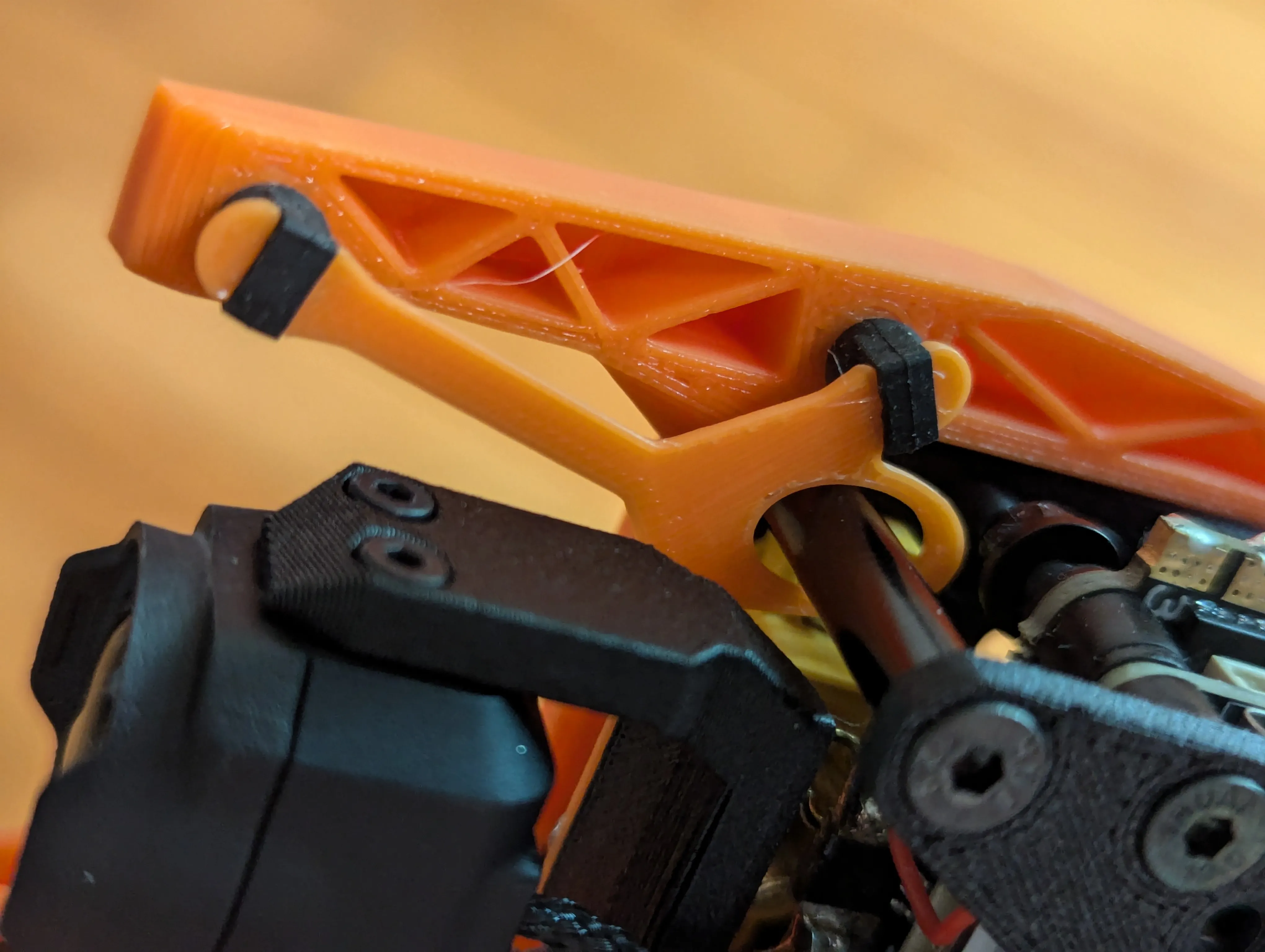
Typical FPV camera mounts bolt the camera rigidly to the frame — sturdy, but every motor vibration reaches the sensor. The Grasshopper5 uses rubber damping balls (same size as DJI AVATA 2 spares) for real vibration isolation and noticeably cleaner video on a DIY build.
Flight controller and ESC
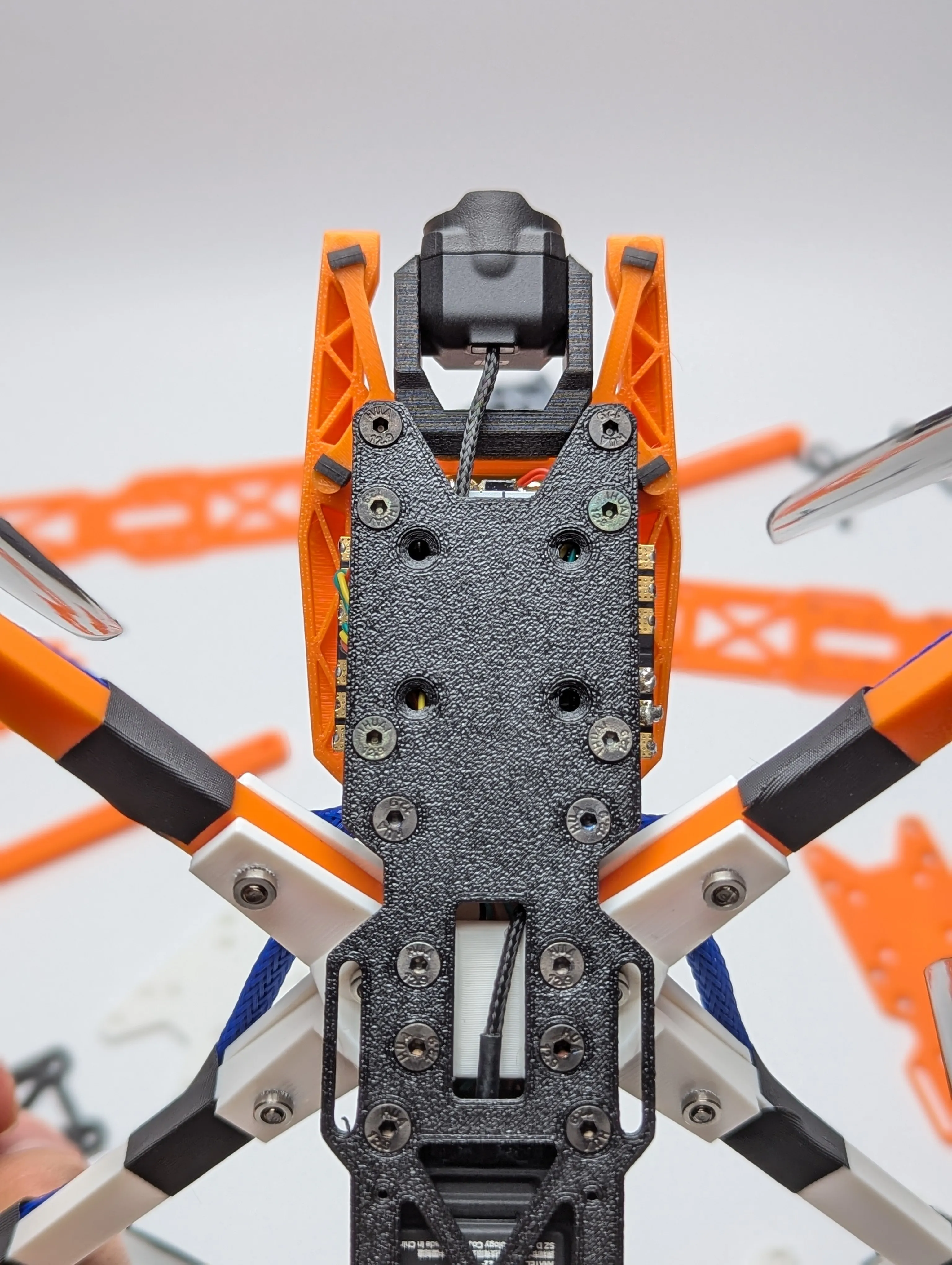
Standard tower stack: 30.5×30.5 and 20×20 holes. The reference build uses the MicoAir H743 V2 on a MicoAir 50A Bluejay 4-in-1 ESC.
Video transmitter and antenna
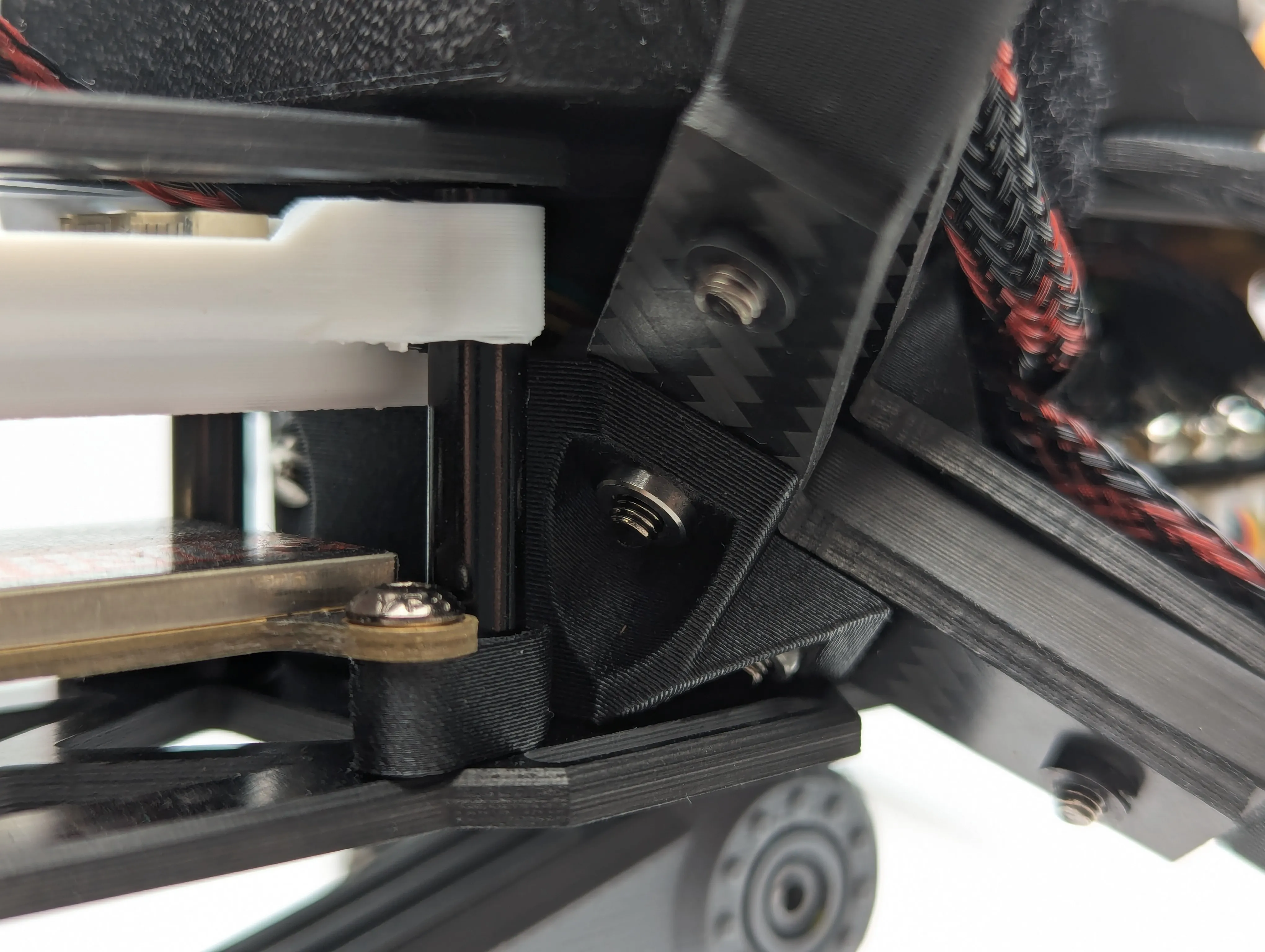
The frame takes both DJI O3 and traditional analog VTX modules, with two mounting positions. For the analog route we now fly our own VT5804 2.5 W VTX with the A5800 omni antenna — 48 channels, SmartAudio power control from the ArduPilot OSD, and enough headroom for genuine long-range work.
Some build photos show the earlier third-party VTX used in the prototype; updated photos with the VT5804 installation are coming.
RC and telemetry
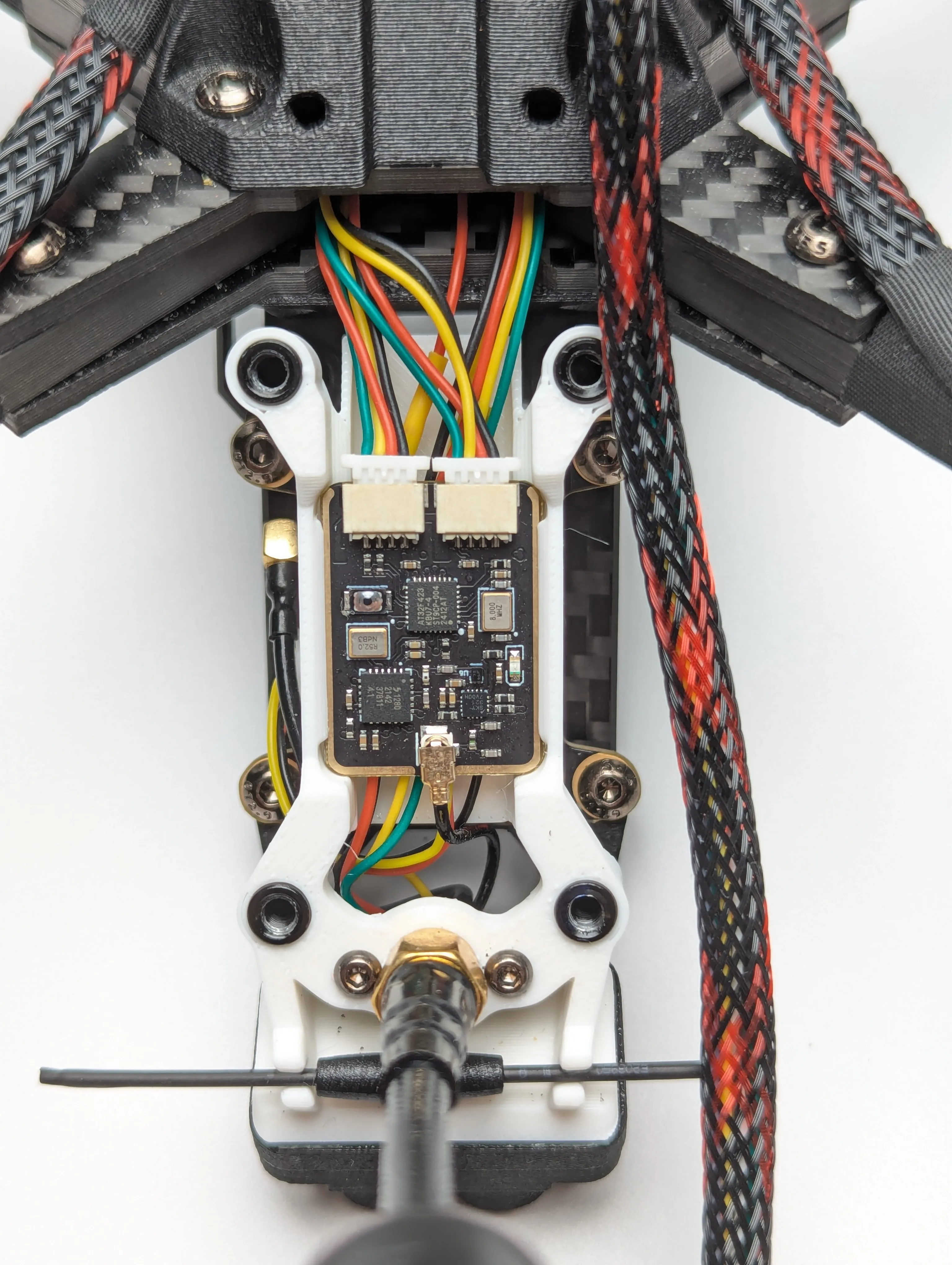
Flying ArduPilot without telemetry wastes half the firmware. The clean solution is a 2-in-1 RC + telemetry link: the MicoAir TRS gives stick control and full MAVLink telemetry (parameters, mission upload, live HUD) over one 2.4 GHz link — one antenna on the airframe, one module in your radio's JR bay.
GPS, compass, optical flow and rangefinder
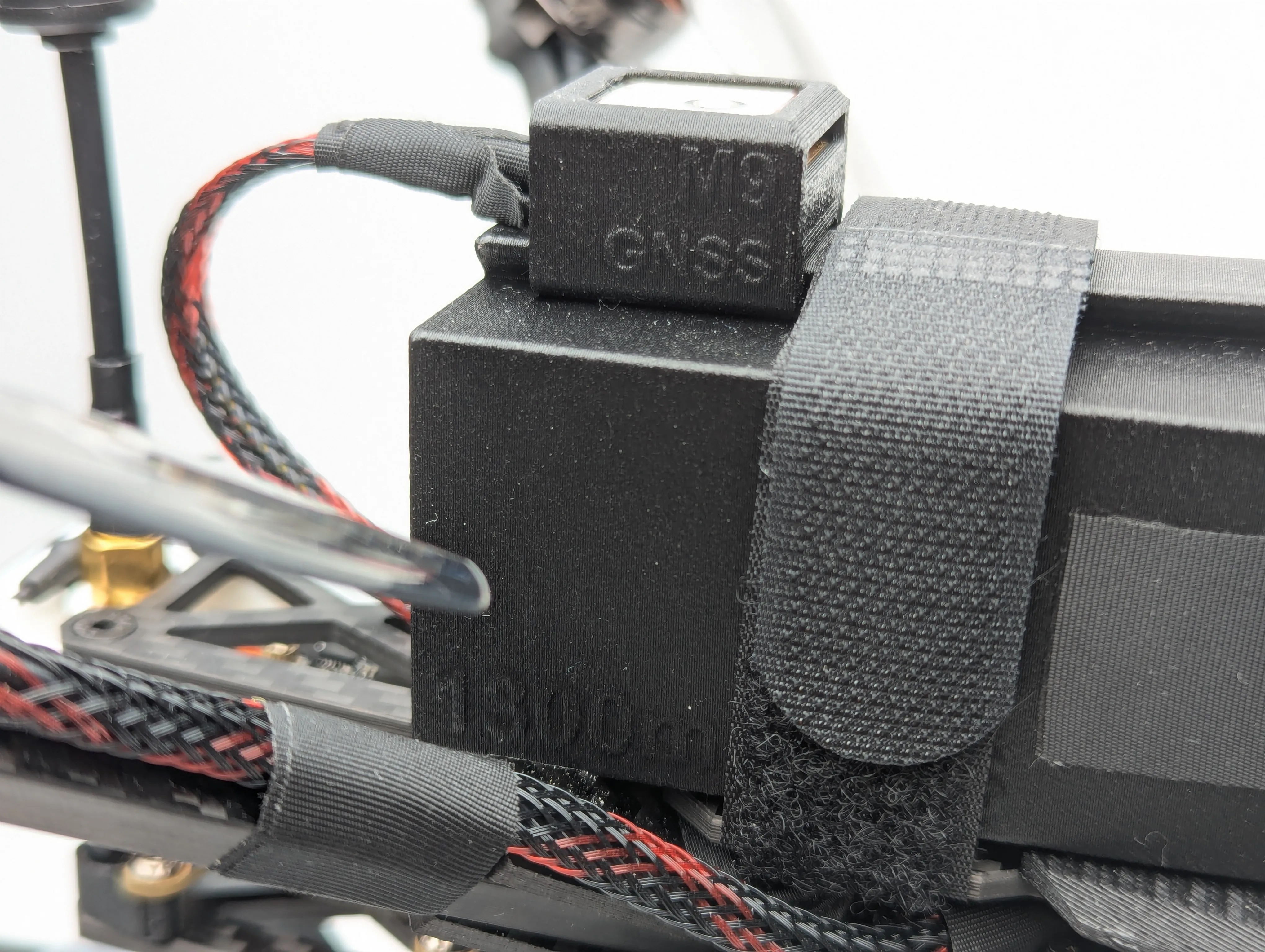
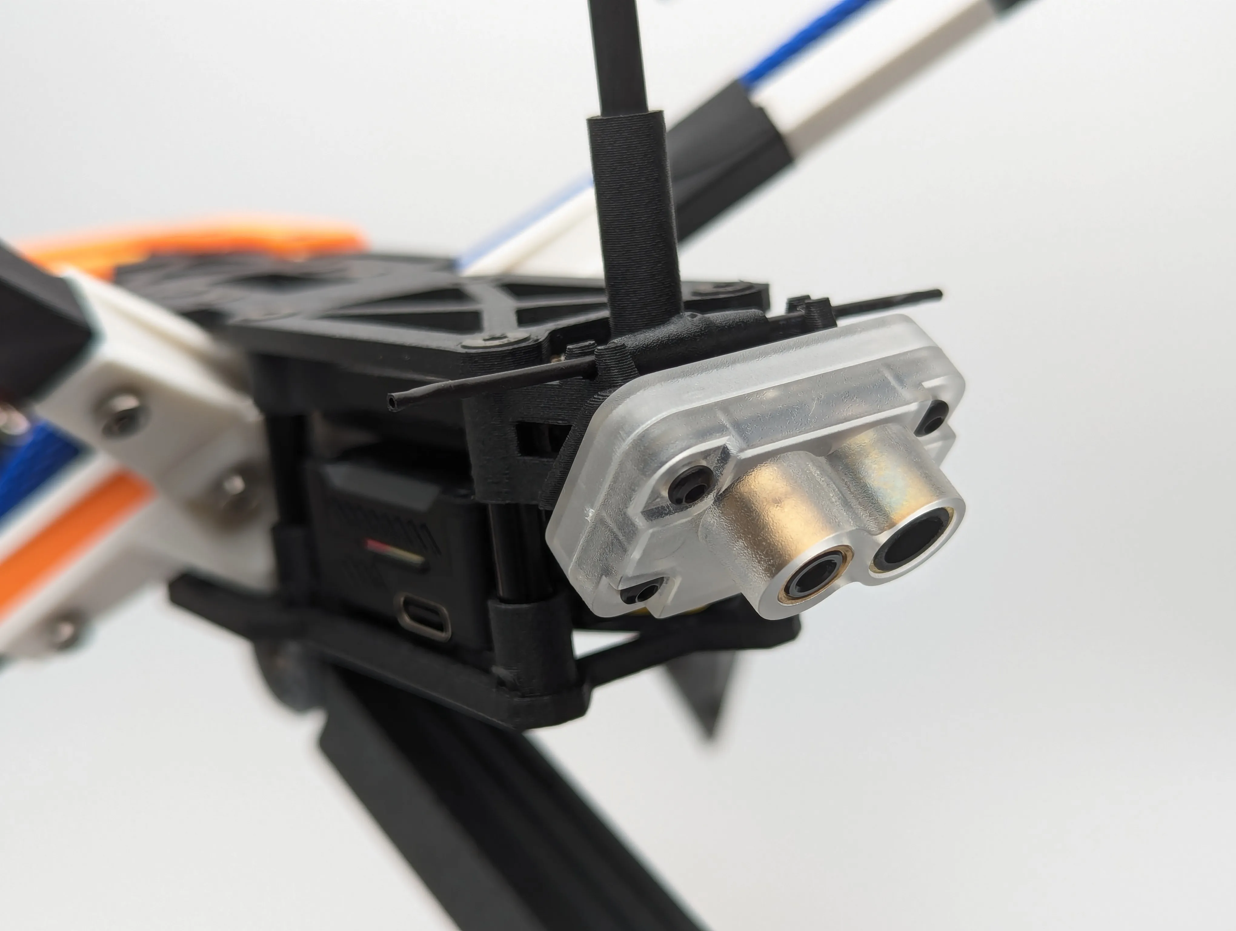
The GPS rides above the battery in a printed protective case — the position that flight testing showed picks up the least motor/ESC interference for both GNSS and compass. At the rear, an MTF-01P optical flow + rangefinder (mount also fits MTF-01/02/02P) covers position hold when GNSS is weak and gives precise altitude hold near the ground — effective to roughly 10 m.
Tilt adjustment
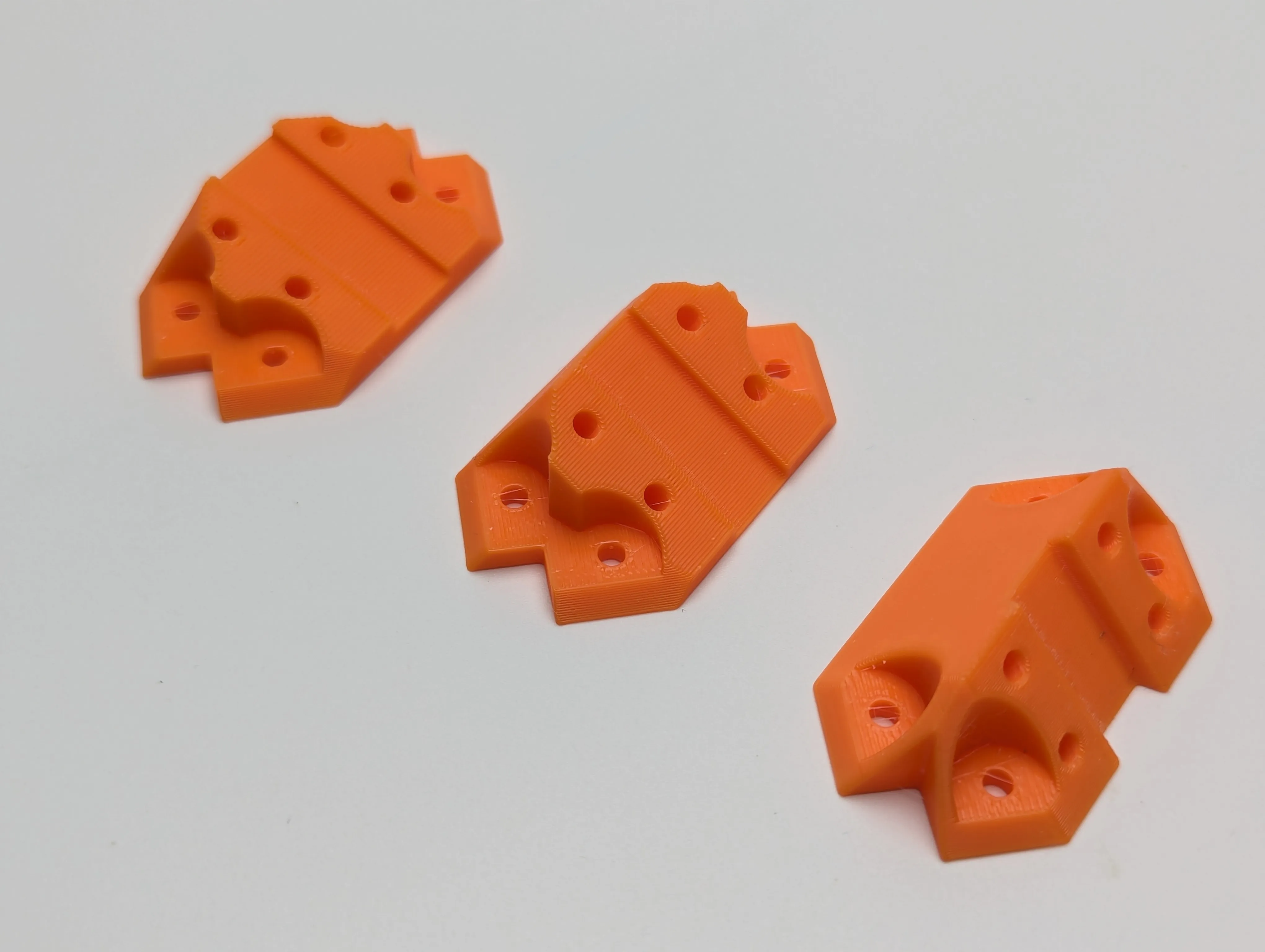
Two symmetric printed parts join the rotor plane to the body. Swap them to change the angle — 20°, 30° and 45° parts are included, and custom angles are a five-minute CAD edit.
Firmware setup — the one special step
Because the FC sits on the body while the props define the rotor plane, you must tell the firmware about the tilt. With a 45° tilt and the FC mounted facing backwards (cleaner wiring):
ArduPilot (compass orientation is auto-detected during calibration):
CUST_ROT_ENABLE = 1
CUST_ROT1_PITCH = -45
CUST_ROT1_YAW   = 180
INAV — set board alignment visually in the configurator (Pitch −45°, Yaw 180° for the same mounting). If using a GPS-compass module, set the compass orientation to match yours.
Betaflight — same values under Configuration → Board and Sensor Alignment.
Verify before you fly
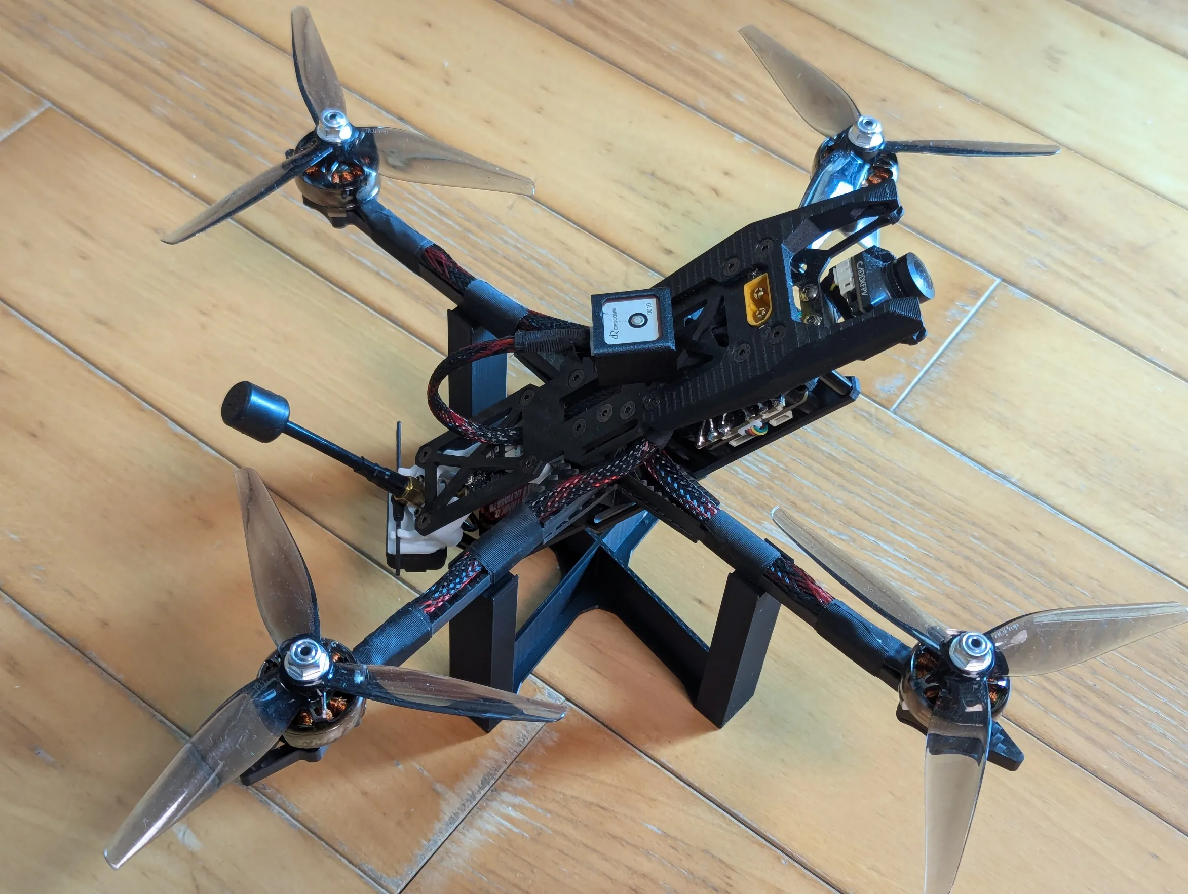
Rest the aircraft so the rotor plane is parallel to the ground (the included "IMU setup and leveling bracket" part does this). Connect to your ground station — the artificial horizon must read level. Then rotate the aircraft in pitch/roll/yaw relative to the rotor plane and confirm the HUD follows. If both check out, the alignment is correct.
3D printing notes
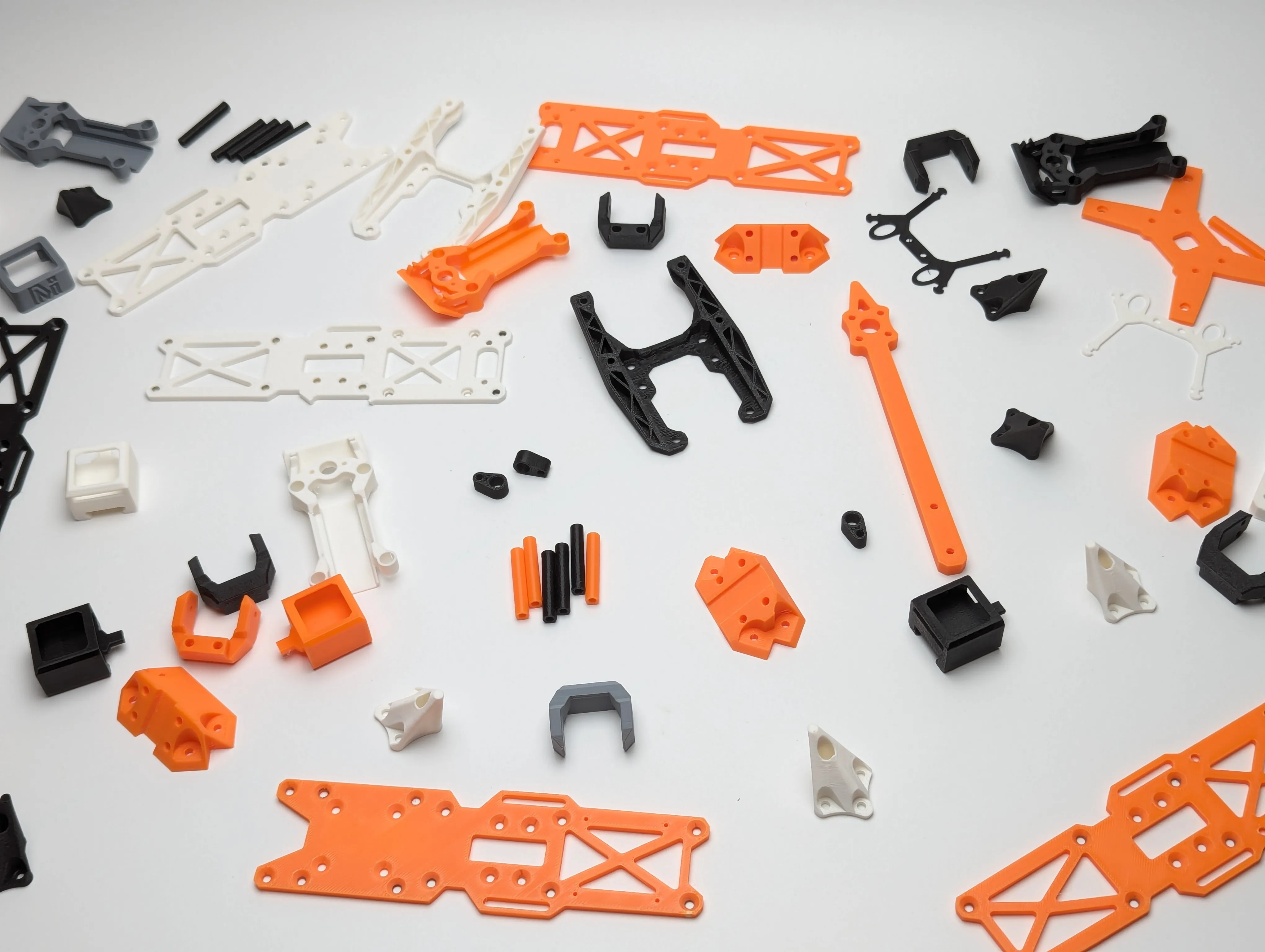
Use ABS or PETG minimum — ABS-CF / PETG-CF preferred. Motor arms and the VTX area see real heat; PLA will not survive. Most parts print support-free; the few that need it use easily-removed base supports. Infill 50–70%. A ready-made print profile (0.2 mm, 4 walls, 75% infill) is on the MakerWorld page.
Bill of materials
| Part | Reference choice | Get it |
|---|---|---|
| Complete electronics | Everything below, bundled | 5-Inch FPV Electronics Kit — from $219.99 |
| Flight controller | MicoAir H743 V2 | Product page · Manual |
| ESC | MicoAir 50A 4-in-1 Bluejay | Product page |
| GPS + compass | M10G-5883 (or MG-F10-C dual-band for sub-meter) | M10G-5883 · MG-F10-C |
| RC + telemetry | MicoAir TRS 2-in-1 | Product page · Manual |
| Video transmitter | Robofusion VT5804 + A5800 antenna | Product page · Manual |
| Optical flow + rangefinder | MicoAir MTF-01P | Product page |
| Motors / props / camera / battery | 2207-class motors, 5" props, analog cam, 6S 1300 mAh | Your choice — any standard FPV parts fit |
FAQ
Can I use the electronics kit with a different frame?
Yes — the kit is deliberately frame-agnostic. Anything with a 30.5×30.5 stack mount works, 5-inch through 7-inch, carbon or printed.
Do I really need the optical flow sensor?
For pure manual FPV, no. For ArduPilot position hold indoors, near the ground, or anywhere GPS gets shaky — it's the difference between a drone that parks itself and one that drifts.
Is the tilted layout faster?
On a 5-inch, treat it as an experiment platform (that's the point of making it printable and adjustable). The aerodynamic payoff grows with frame size and cruise speed — which is where this project line is heading.
What's next
This is the first entry in our Projects series. On the roadmap: structural optimization, wing add-ons for forward-flight efficiency, control surfaces — and a complete ArduPilot fixed-wing build series (assembly → setup → first flight → range testing). New projects and field notes go out to our email subscribers first — subscribe at robofusion.ca.
Downloads & links
- STL files + print profile + assembly PDF (MakerWorld)
- All Robofusion designs on MakerWorld
- License: CC BY-NC 4.0
Designed, built and flown by the Robofusion engineering team.
Written and maintained by the Robofusion engineering team.
New builds, design updates and field-test results go to subscribers first. No spam — a couple of emails a month, unsubscribe anytime.
Comments & build logs
Built one? Questions about the setup? Post below — sign in with GitHub.