A5800 5.8 GHz FPV Antenna — Lab Test Report & Guide
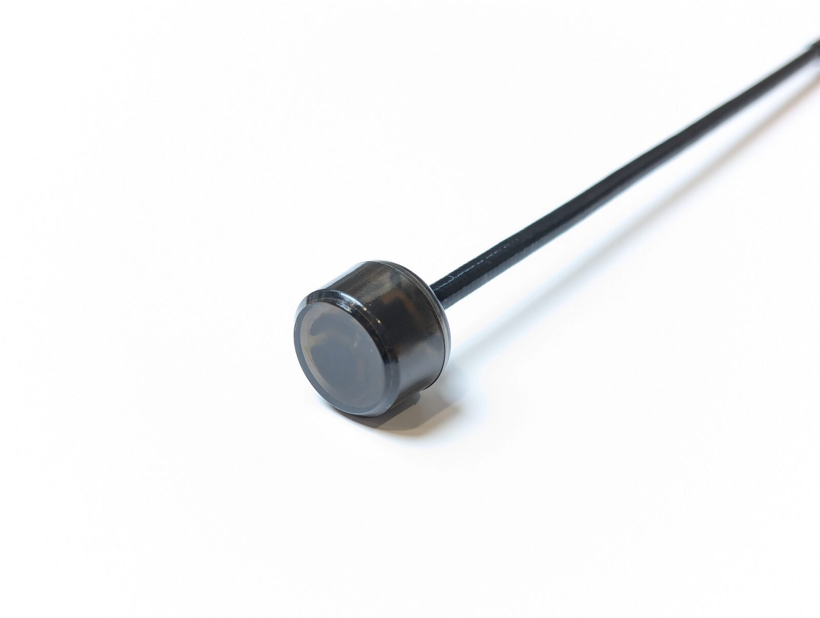
The A5800 is a 5.8 GHz omnidirectional dipole antenna built with LDS (Laser Direct Structuring) technology inside a semi-transparent protective radome. It is the matching antenna for the VT5804 (2.5 W) and VT5805 (4 W) video transmitter modules.
This page reproduces the complete manufacturer approval test report — VSWR, gain, radiation efficiency, and full radiation patterns, all measured in a calibrated anechoic chamber — with plain-English explanations of what each measurement means. Most FPV antennas are sold on marketing claims; this one comes with data.
Where to buy
- Robofusion store (ships from Canada — free Canada-wide shipping): A5800 5.8 GHz FPV Antenna (2-Pack) — also available as a bundle option on the VT5804 and VT5805 product pages
Specifications at a glance
| Item | Specification |
|---|---|
| Antenna type | Dipole, omnidirectional (LDS) |
| Design frequency range | 5350–5850 MHz |
| Peak gain | 3.0 dBi nominal (3.56 dBi measured) |
| Radiation efficiency | > 60 % across the band (max 83.6 %) |
| VSWR | < 2.0 across 5350–5850 MHz (measured 1.25–1.87) |
| Impedance | 50 Ω |
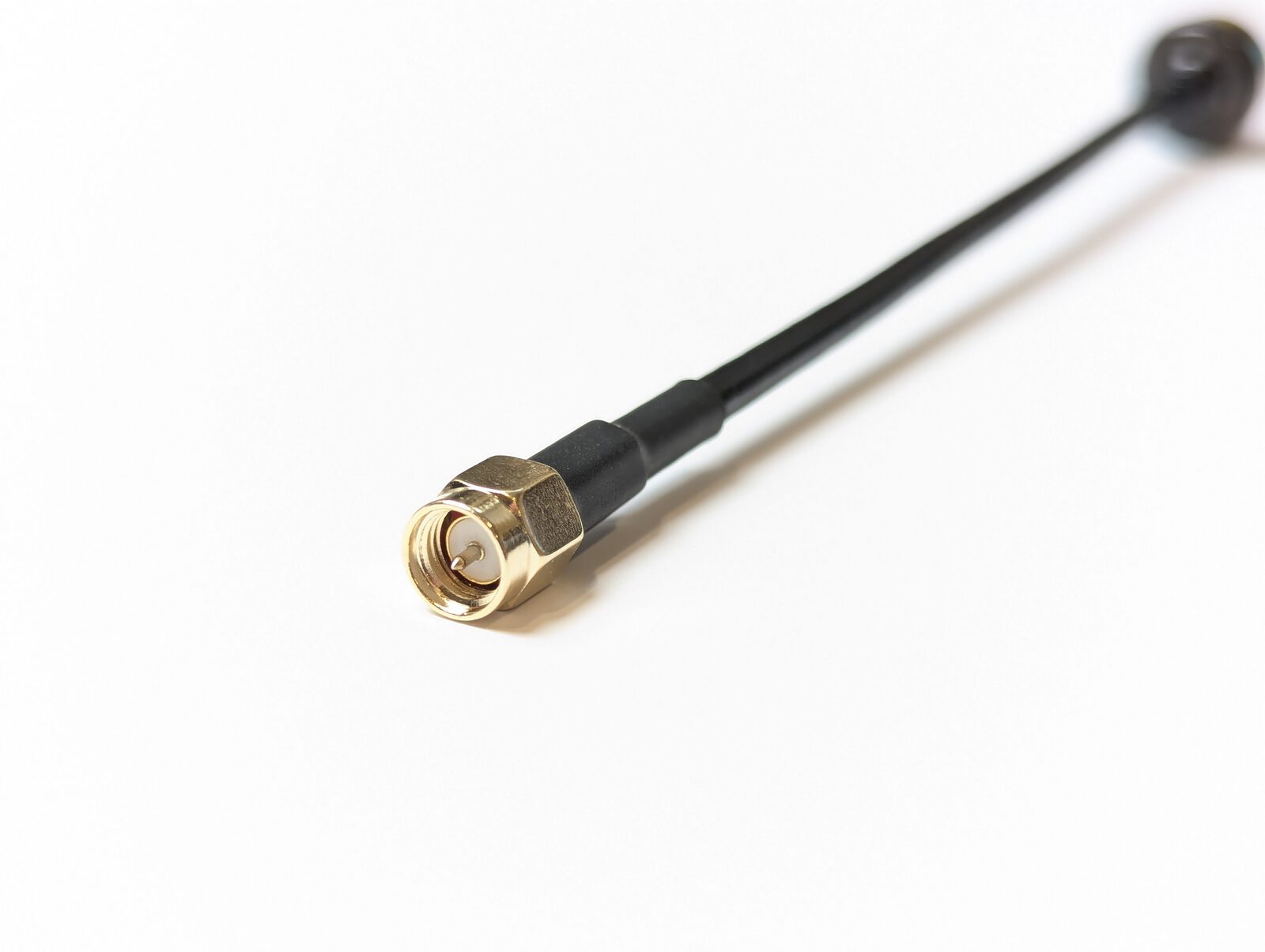
| Connector | SMA (male pin) |
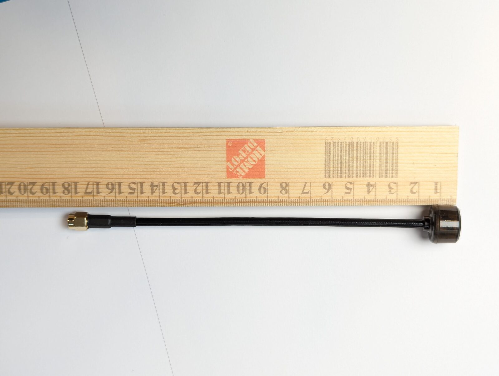
| Overall length | 178 ± 1.0 mm |
| Radome head diameter | Ø18.27 mm |
| Connector hex | 8.0 ± 0.05 mm |
| Cable | RG141, black, with black heat-shrink strain relief |
| Housing | Semi-transparent radome |
| Operating temperature | −30 °C to +85 °C |
| Storage temperature | −30 °C to +85 °C |
| Packaging | Individually bagged |
Laser Direct Structuring draws the antenna's radiating element directly onto a molded plastic carrier with a laser, then metallizes the traced path. Compared with hand-formed wire whips, every unit comes out geometrically identical — which is why the tuning (VSWR and efficiency) stays consistent from antenna to antenna. It's the same process used for the internal antennas in most modern smartphones.
How this antenna was tested
All data below comes from the manufacturer's antenna laboratory, measured with calibrated instruments:
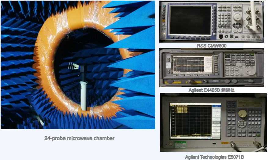
- 24-probe microwave anechoic chamber — gain, efficiency, and radiation patterns
- Agilent Technologies E5071B vector network analyzer — VSWR / impedance matching
- Agilent E4405B spectrum analyzer and R&S CMW500 radio tester — supporting RF measurements
The blue foam spikes absorb virtually all RF reflections, so the only signal the probes see is what the antenna itself radiates — no echoes off walls, floors, or equipment. The 24 probes ring the antenna and sample its radiation from all directions at once, which is how the 3D pattern and true radiation efficiency are captured. You cannot measure these numbers meaningfully on a bench.
VSWR — how well the antenna is matched
When a transmitter pushes power into an antenna, any impedance mismatch reflects part of that power straight back into the transmitter. VSWR (Voltage Standing Wave Ratio) measures this: 1.0 is a perfect match (nothing reflected), 2.0 — the industry bar for "good" — means about 11 % of power is reflected, and high VSWR both wastes range and heats the VTX output stage. This is also why you never power a VTX without an antenna: no antenna is an extreme mismatch, and at 2.5–4 W the reflected power destroys the transmitter. A low-VSWR antenna like this one is cheap insurance for a high-power module.
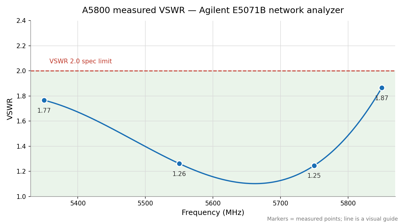
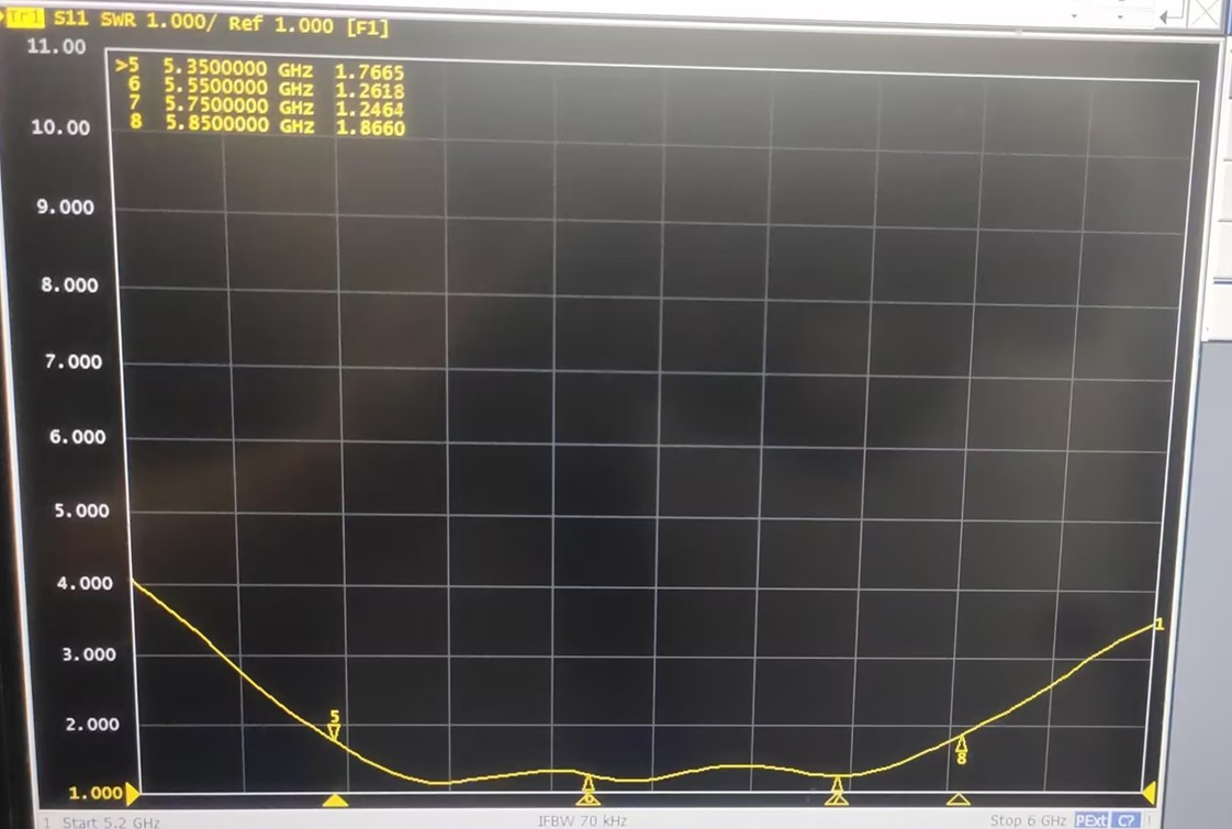
Measured on the Agilent E5071B across the design band:
| Frequency | Measured VSWR | Reflected power |
|---|---|---|
| 5350 MHz | 1.77 | ~7.7 % |
| 5550 MHz | 1.26 | ~1.3 % |
| 5750 MHz | 1.25 | ~1.2 % |
| 5850 MHz | 1.87 | ~9.1 % |
The match is deepest in the middle of the band — around Raceband and FS/IRC frequencies — exactly where most pilots fly. Original network-analyzer capture:
Gain and radiation efficiency
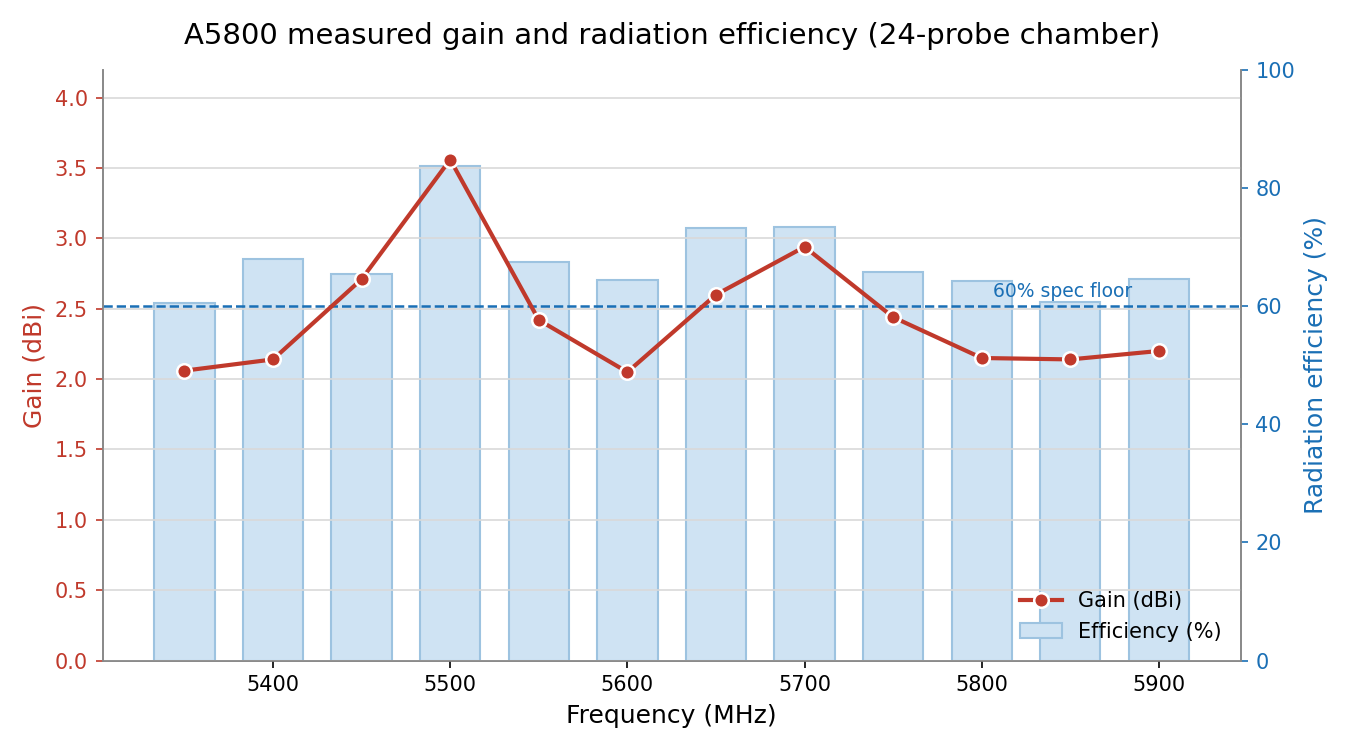
Gain describes how the antenna concentrates energy, measured in dBi — decibels relative to a theoretical antenna that radiates equally in every direction (a perfect sphere). A dipole doesn't radiate up and down its own axis, so that energy is redistributed toward the horizon — that redistribution is the ~2–3 dBi. Radiation efficiency is simpler: of the power delivered to the antenna, how much actually leaves as radio waves instead of turning into heat? Cheap FPV whips often sit at 30–50 %; anything above 60 % across a whole band is a well-engineered antenna. Note that for an omni, more gain is not automatically better — see the FAQ below.
Measured in the 24-probe chamber at 12 points across (and beyond) the design band:
| Frequency (MHz) | Gain (dBi) | Efficiency (%) |
|---|---|---|
| 5350 | 2.06 | 60.5 |
| 5400 | 2.14 | 68.0 |
| 5450 | 2.71 | 65.4 |
| 5500 | 3.56 | 83.6 |
| 5550 | 2.42 | 67.4 |
| 5600 | 2.05 | 64.5 |
| 5650 | 2.60 | 73.2 |
| 5700 | 2.94 | 73.4 |
| 5750 | 2.44 | 65.8 |
| 5800 | 2.15 | 64.3 |
| 5850 | 2.14 | 60.7 |
| 5900 | 2.20 | 64.6 |
Every point clears the 60 % efficiency floor — including 5900 MHz, above the formal design band.
Radiation patterns — where the signal actually goes
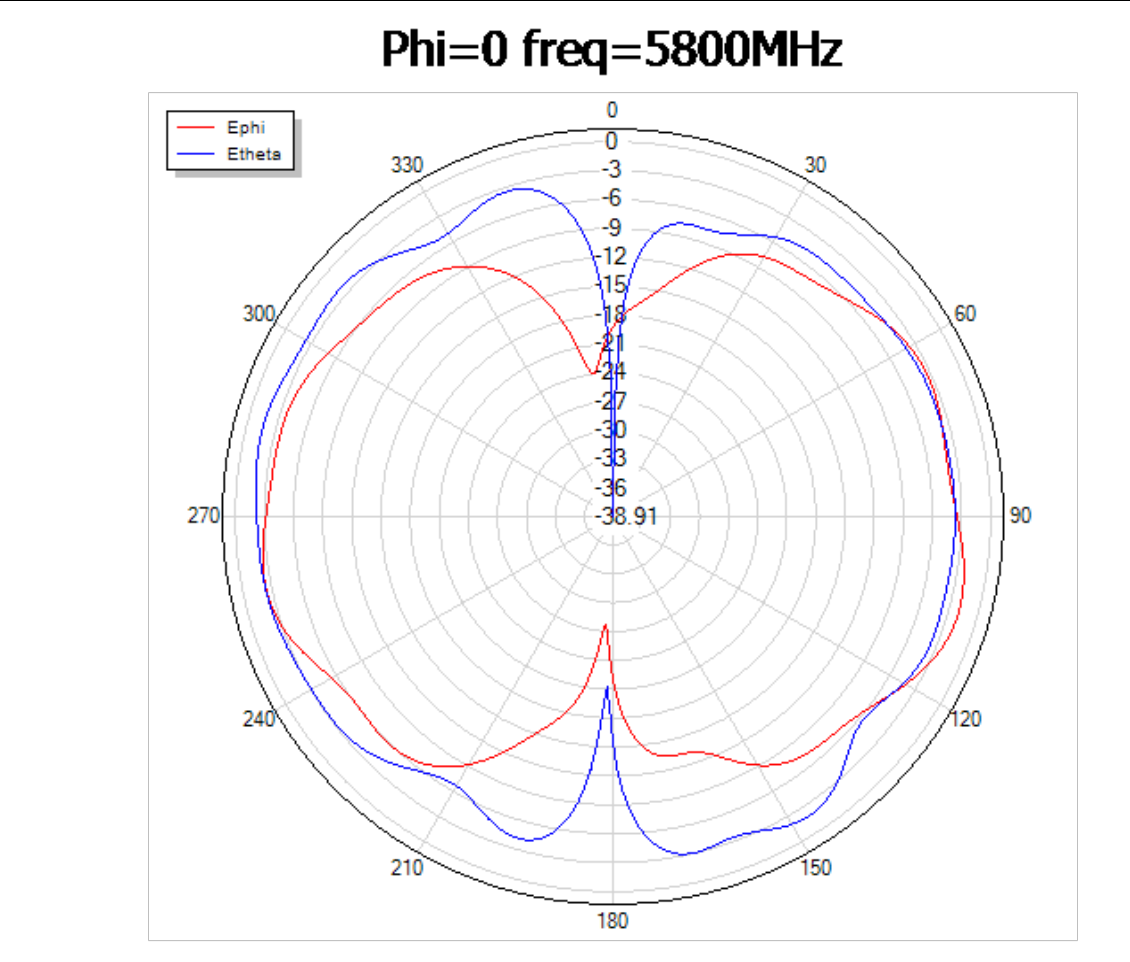
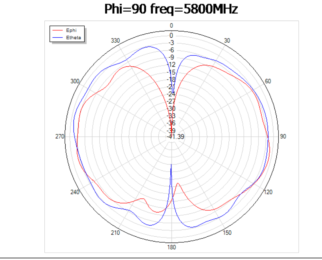
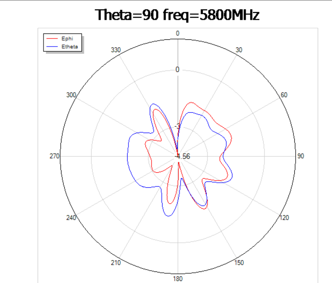
A radiation pattern is a slice through the antenna's "signal balloon". The antenna sits at the center; the farther the curve reaches toward the edge at a given angle, the stronger the signal in that direction (radial scale in dB). Phi = 0° and Phi = 90° are two vertical slices (side views, 90° apart); Theta = 90° is the horizontal slice (top-down view). The red (Ephi) and blue (Etheta) traces are the two polarization components of the field. All patterns below were measured at 5800 MHz.
Vertical cuts — the classic dipole "figure-8": strong toward the horizon, nulls along the antenna's axis (straight up and down the radome):
Horizontal cut — seen from above, coverage is spread around the full 360°, which is what "omnidirectional" means in practice:
3D pattern — the full measured balloon (peak 3.56 dBi, deepest null −24.47 dBi), the donut shape every well-behaved dipole should produce:
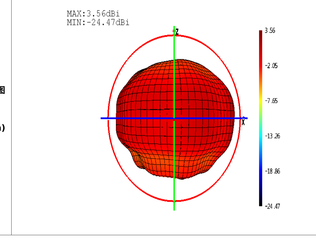
Because the nulls sit off the antenna's tip, the worst thing you can do is point the tip at your ground station. Mount the antenna vertically (radome up or down) so the pattern's strong equator sweeps the horizon — signal then stays steady as the aircraft turns. Use the same orientation on both ends of the link: vertical in the air, vertical on the ground.
Matching circuit
The approval sheet documents the antenna's matching network position (a standard π-network footprint between the RF module and the antenna, 0402 components E1/E2/E3):
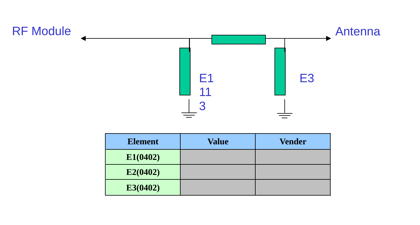
Per the manufacturer: no matching components were needed — the LDS element is tuned to 50 Ω as designed, and the E1/E2/E3 positions ship unpopulated. That's the cleanest possible result: matching networks exist to correct an antenna's impedance, and every added component costs a little efficiency.
Structure and materials
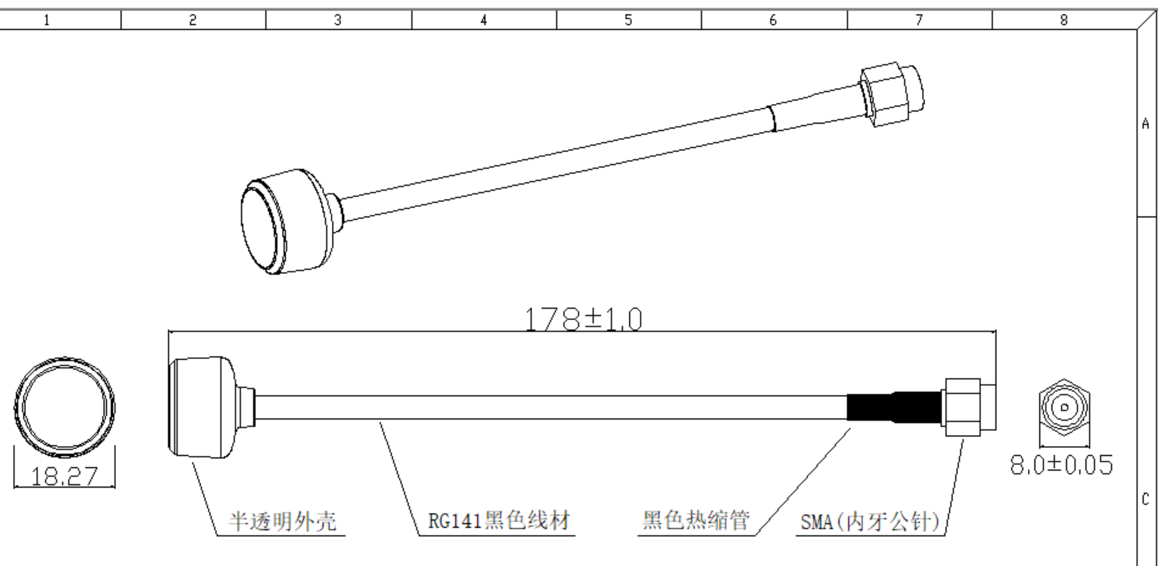
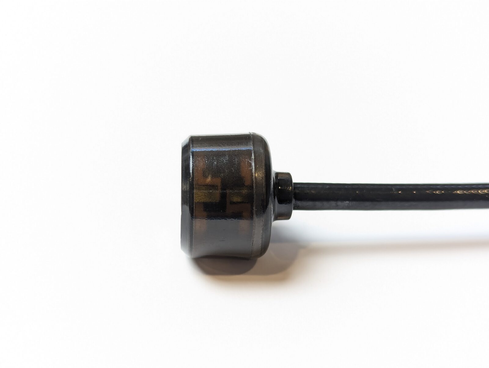
The approval-sheet structure drawing, and the production antenna it describes:
| Feature | Detail |
|---|---|
| Overall length | 178 ± 1.0 mm |
| Radome | Semi-transparent shell, Ø18.27 mm head — the LDS element is visible inside |
| Cable | RG141 black coaxial lead |
| Strain relief | Black heat-shrink over the cable-to-connector junction |
| Connector | SMA, male center pin, 8.0 ± 0.05 mm hex |
RG141 is a stiff-but-formable coax: bend it gently to route the antenna, and it holds position. Avoid repeated sharp bends at the same spot.
Band coverage on the VT5804 / VT5805
The design band of 5350–5850 MHz covers the LOW band, Raceband, FS/IRC, and A/B bands — everything a North American pilot normally flies. The three highest E-band channels (5905 / 5925 / 5945 MHz) sit above the design band; the antenna still measured 2.20 dBi and 64.6 % efficiency at 5900 MHz, but performance on those channels is not guaranteed. See the 48-channel frequency table.
FAQ
Is 3 dBi "low" compared to higher-gain antennas?
No — for an aircraft-side omni it's the right number. Higher-dBi omnis squeeze the donut flatter: more range on the horizon, but deeper nulls above and below, so video drops out when the aircraft banks or flies overhead. 2–3 dBi is the standard choice on the airframe; save high gain for a directional antenna on the ground station.
Why does VSWR matter more on a 2.5 W / 4 W VTX than on a 25 mW one?
Reflected power scales with transmit power. At 25 mW, a poor match wastes a few milliwatts; at 4 W, the same mismatch pumps hundreds of milliwatts of heat back into the output stage. High-power modules need well-matched antennas — it's a reliability issue, not just a range issue.
Does it fit my VT5804 / VT5805?
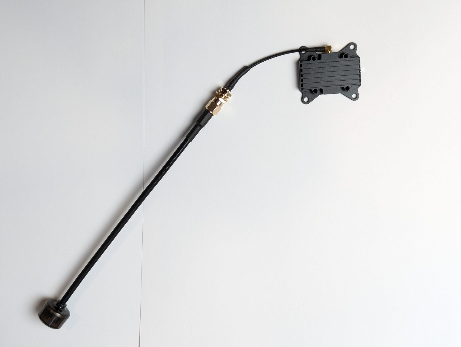
Yes — connect it via the MMCX-to-RP-SMA extension feeder included with both modules. Check the connector pairing on your feeder before flying: the antenna is SMA with a male center pin.
Is this antenna linearly or circularly polarized?
Linearly polarized, like all simple dipoles. Match orientation on both ends (vertical–vertical) for best results. Circularly polarized antennas (the mushroom-shaped ones) reject multipath better in tight proximity flying but give up some efficiency; for long-range line-of-sight work a well-made linear dipole is the standard aircraft choice.
Can I use it for 2.4 GHz RC or 915 MHz telemetry?
No. An antenna only works near its design frequency — at 2.4 GHz or 915 MHz this antenna would reflect most of the power back. Use the antennas supplied with your RC/telemetry gear.
How durable is the radome?
The semi-transparent housing protects the LDS element from impacts and weather across −30 °C to +85 °C. Carry the antenna by the body, not the radome tip, and check the SMA nut for tightness before each session.
Related guides
- VT5804 5.8 GHz 2.5W Video Transmitter — User Manual
- VT5805 5.8 GHz 4W Video Transmitter — User Manual
- ArduPilot — Telemetry Setup Guide
Written and maintained by the Robofusion engineering team. Test data from the manufacturer's antenna laboratory approval sheet (March 2026).